

DIY Motion Simulator
- Part 1 – Project overview – What is it and what is it so much fun? 😉
- Introduction, what is this about?
- Showcase of the completed project (with video!)
- The “SFX-100” project
- Bill of materials and cost breakdown
- 3D printed parts
- Competitive landscape and price comparison
- Manuals for motors and controllers (download links)
- Part 2 – Electronics
- Part 3 – Linear actuators
- Part 4 – The rig
This is a part 2 of 4 – access all the sections of this series by using the index above.
Part 2 – Electronics, motor wiring and testing, enclosure
I recommend starting the work on this project by doing the electronics first. Once you order all the parts, you should be able to receive Arduino and even custom fabricated PCB before the motors and other hardware arrives from China. This way we can have first part of the build completed and test motors as soon as they arrive, to minimize the time it takes to complete the build.
Please see the bill of materials for links to all required components.
SFX Breakout Board by Pyronious
I mentioned before the PCB by Pyronious. It’s a great improvement to the SFX-100 build. It serves as a replacement for the breadboard approach for wiring the data to motors. Not only you won’t have to do all of the wiring yourself, but the end result is much more compact. And it doesn’t introduce increase in cost – you simply don’t need to purchase other parts which are now being taken care of by the PCB (whiteboard, wires, WAGO connectors, etc.).
You can learn more about this board on the official website:
https://github.com/Pyronious/SFX-100-Breakout-Board
Go ahead and download the Eagle or Gerber files:
https://github.com/Pyronious/SFX-100-Breakout-Board/tree/master/Group%20Buy%20Edition
Then upload them to a fabrication service of your choice – I’ve been using OSHPark:
https://oshpark.com/
While you have the Github repo open, be sure to also download STLs for the enclosure and 3D print it:
https://github.com/Pyronious/SFX-100-Breakout-Board/tree/master/Group%20Buy%20Edition/Enclosure
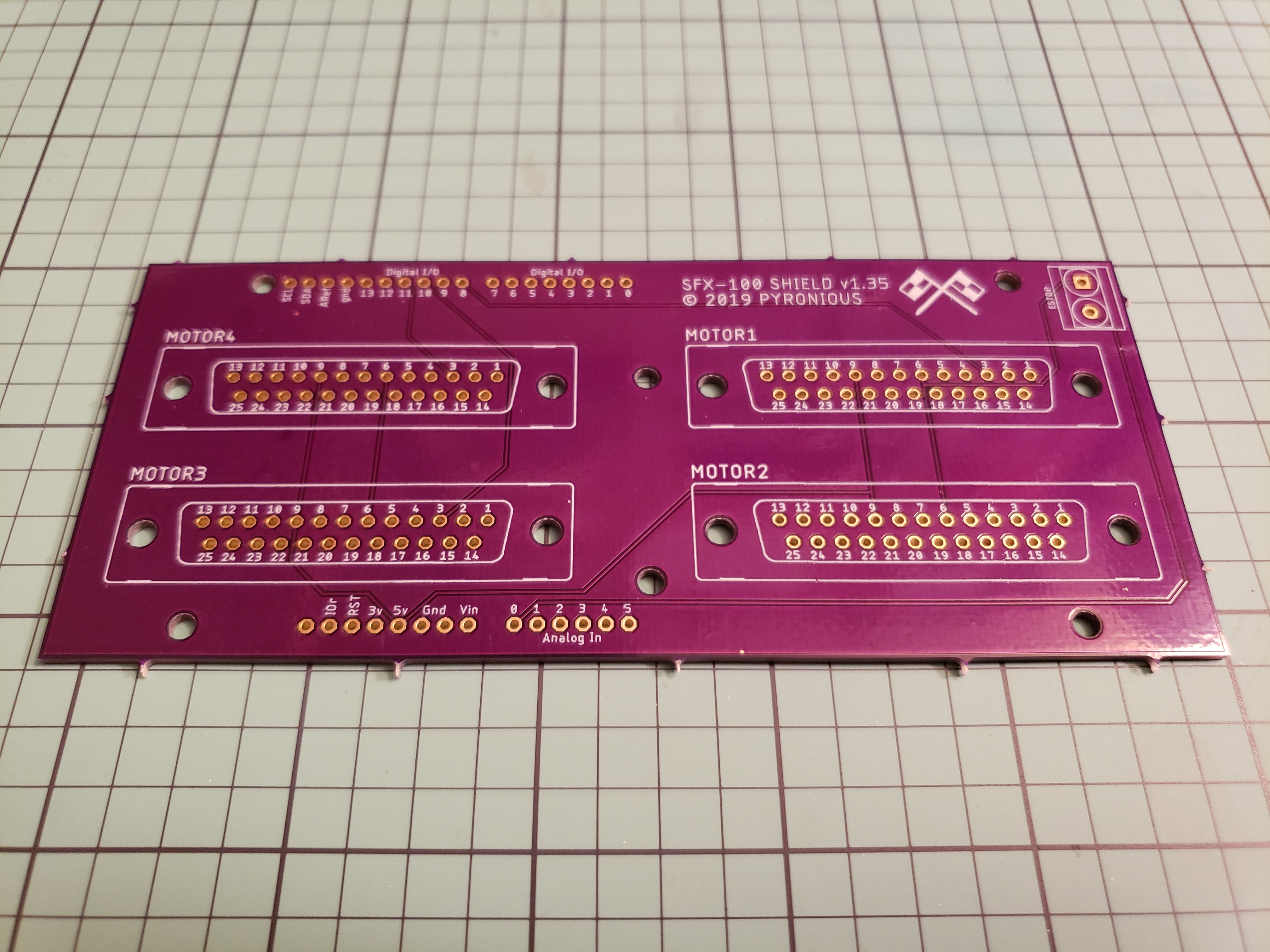
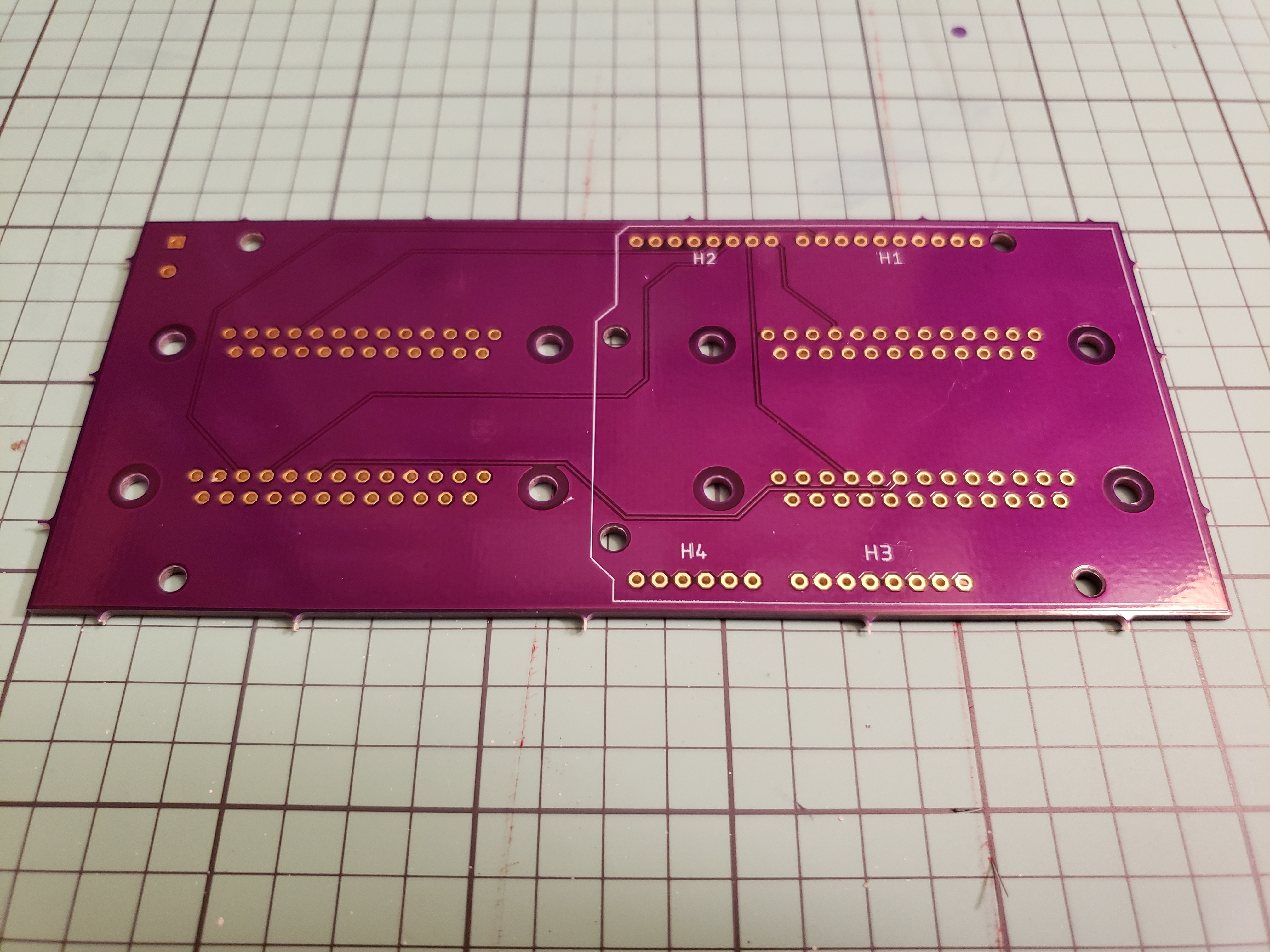
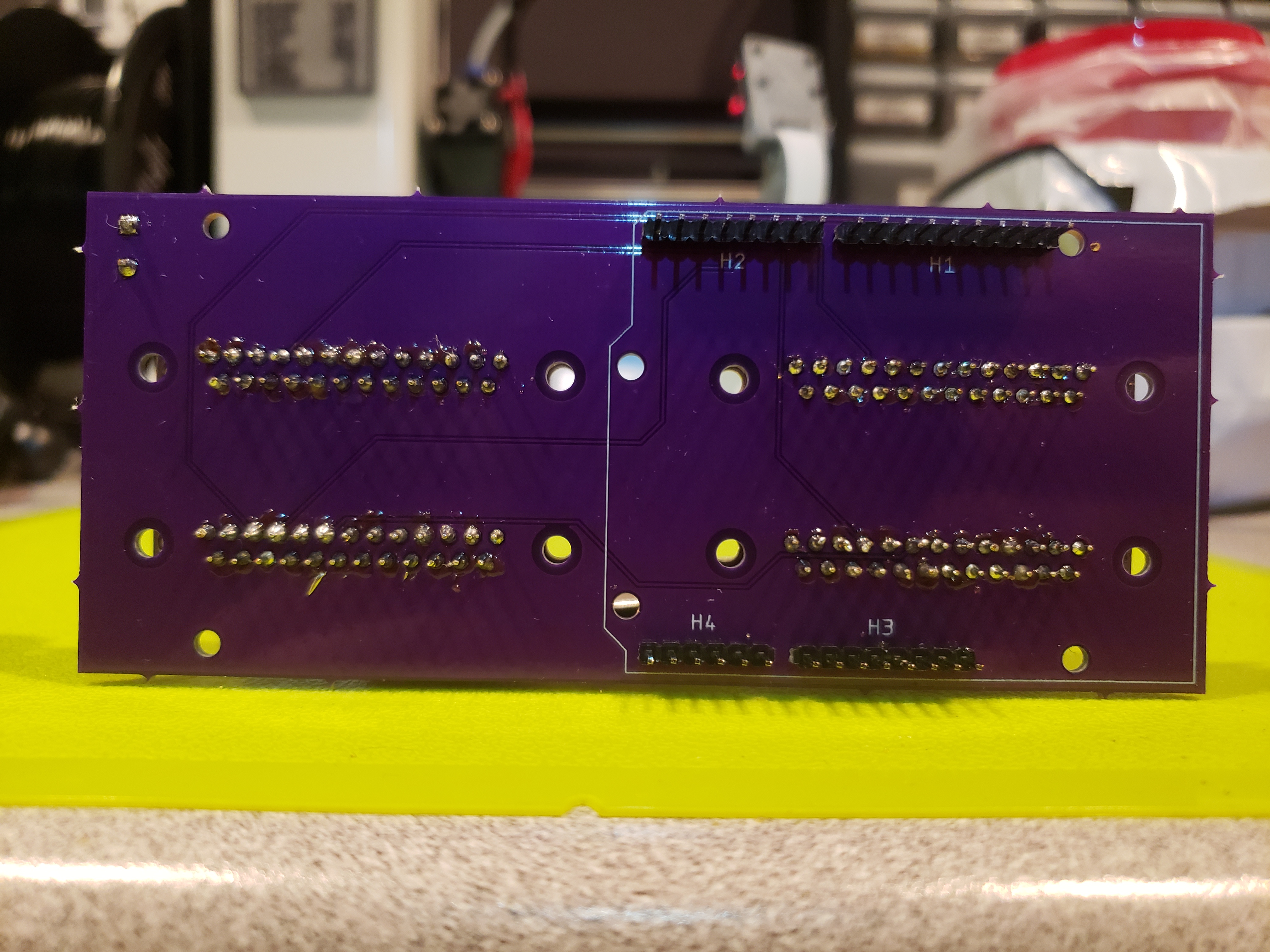
Soldering the board
The boards I had ordered from OSHPark are purple – I like how they look 😉
When ordering from OSHPark, we have to meet requirement of minimum surface area for the ordered PCBs, and order them in multiplies of 3:
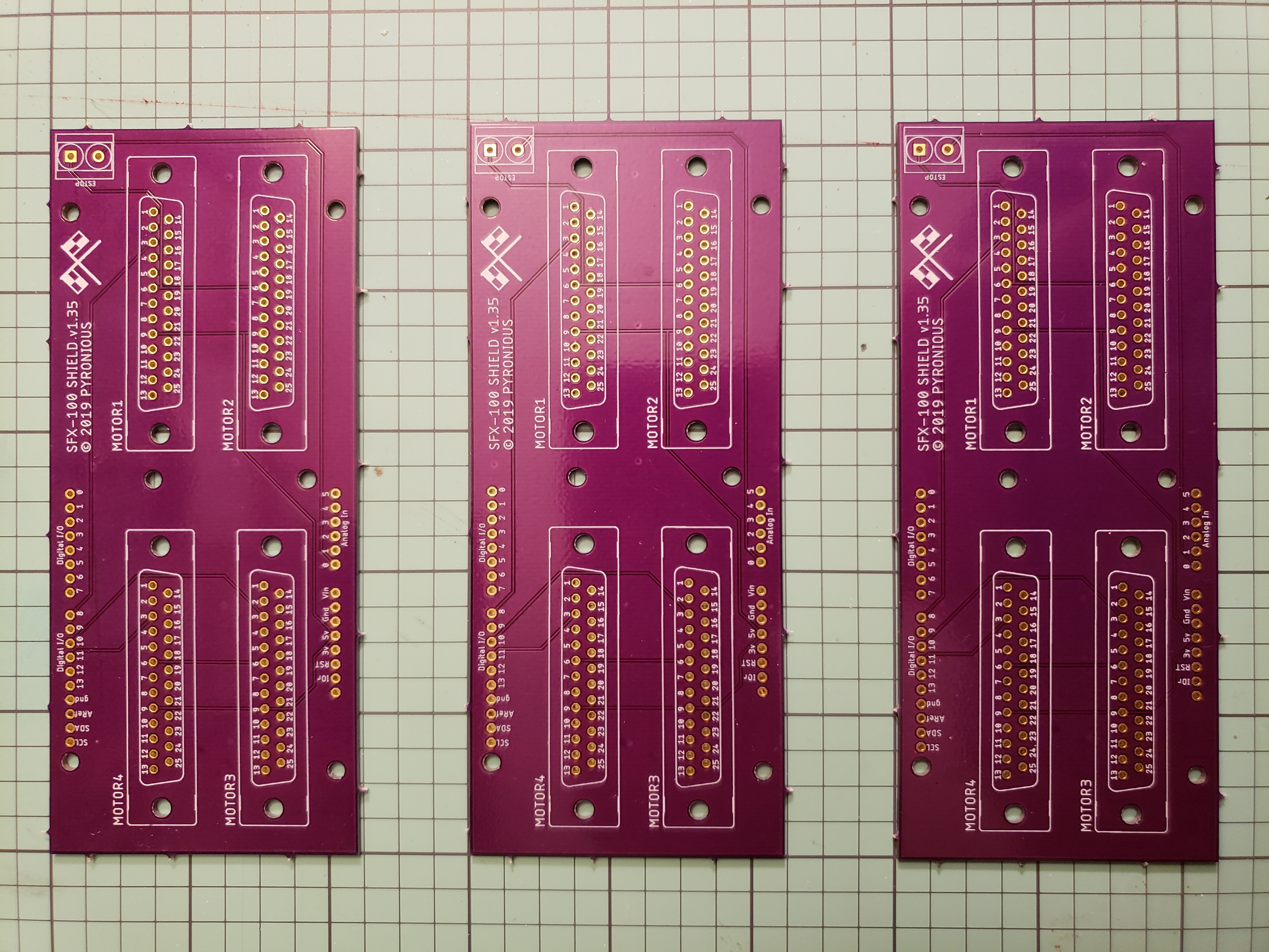
This gives us the comfort of having a spare if something goes wrong, or sharing them with fellow sim racers considering taking on this build.
Let’s grab our trustworthy Arduino Leonardo (ignore the USB cable on the photo, that one won’t be needed, it’s for Arduino Uno R3 which we’re not using):

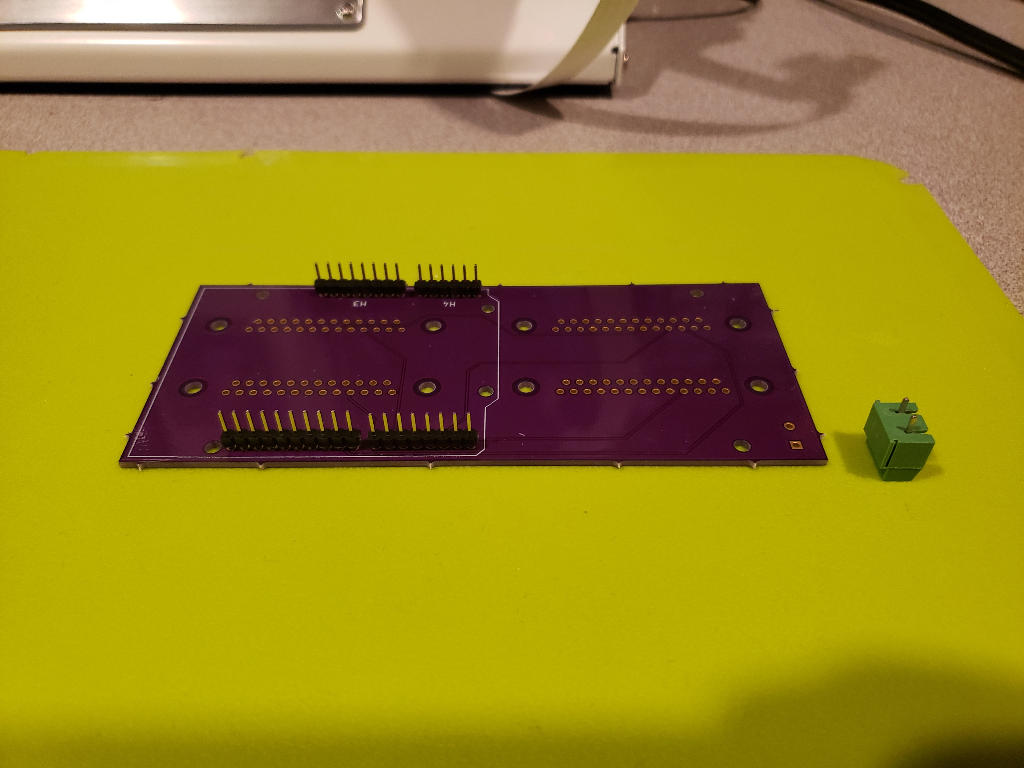
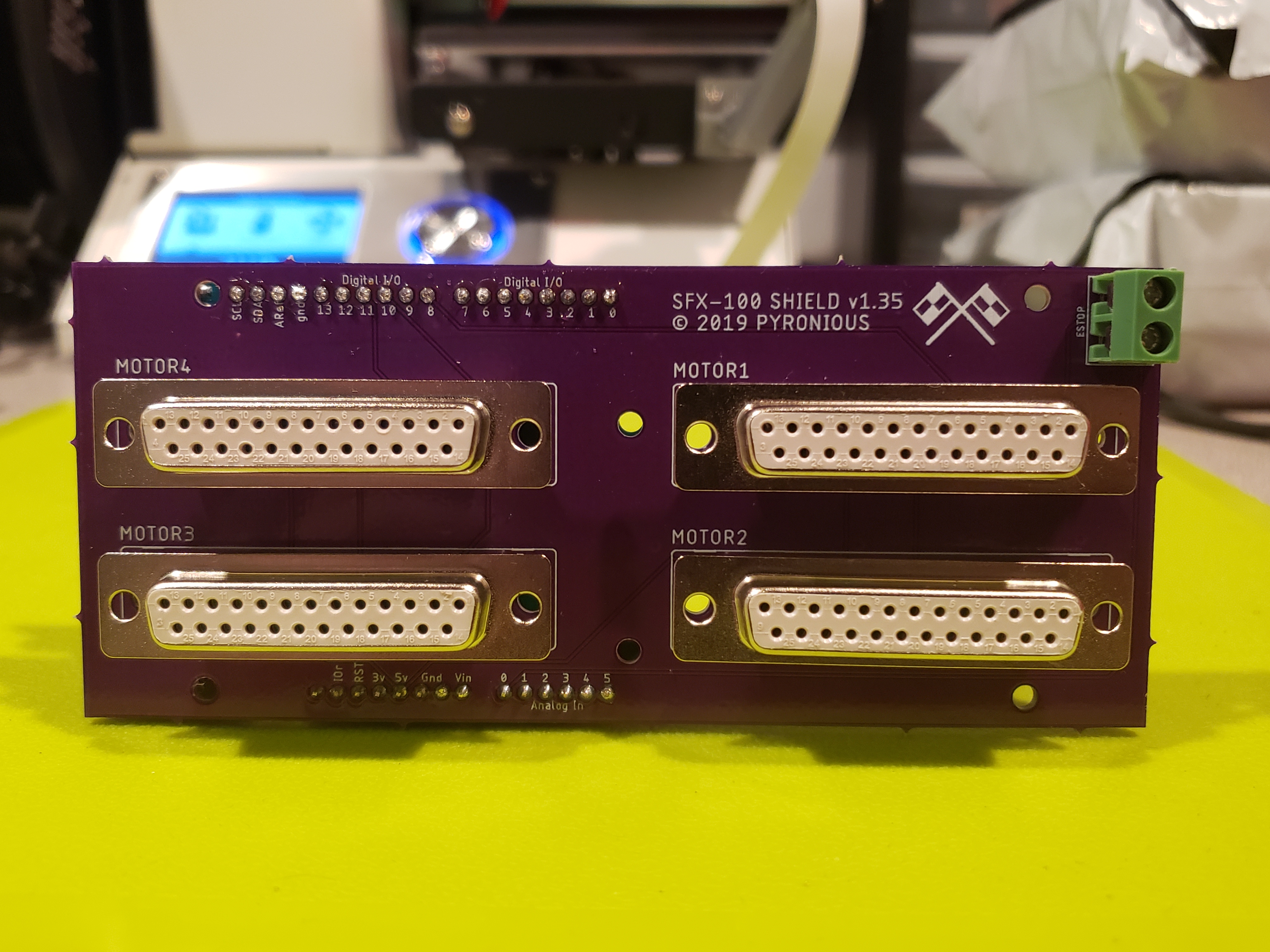
We need to solder the headers, 2-pin connector for emergency stop switch, and 4x female DB25 connectors:
When buying the DB25 connectors, make sure you’re purchasing a variant to be mounted onto PCB. If it mentions “for soldering” in the description, it’s not the one we need – those have small “cups” for each pin that allow for easy soldering of wires to them. However, their pitch is different than in version for PCB mounting, and as such wouldn’t fit onto the board. Please see bill of materials for links to online store I sourced mine from.
Here’s a comparison between both variants:

Left – solder type connector (wrong), right – PCB mount type (the one we need).
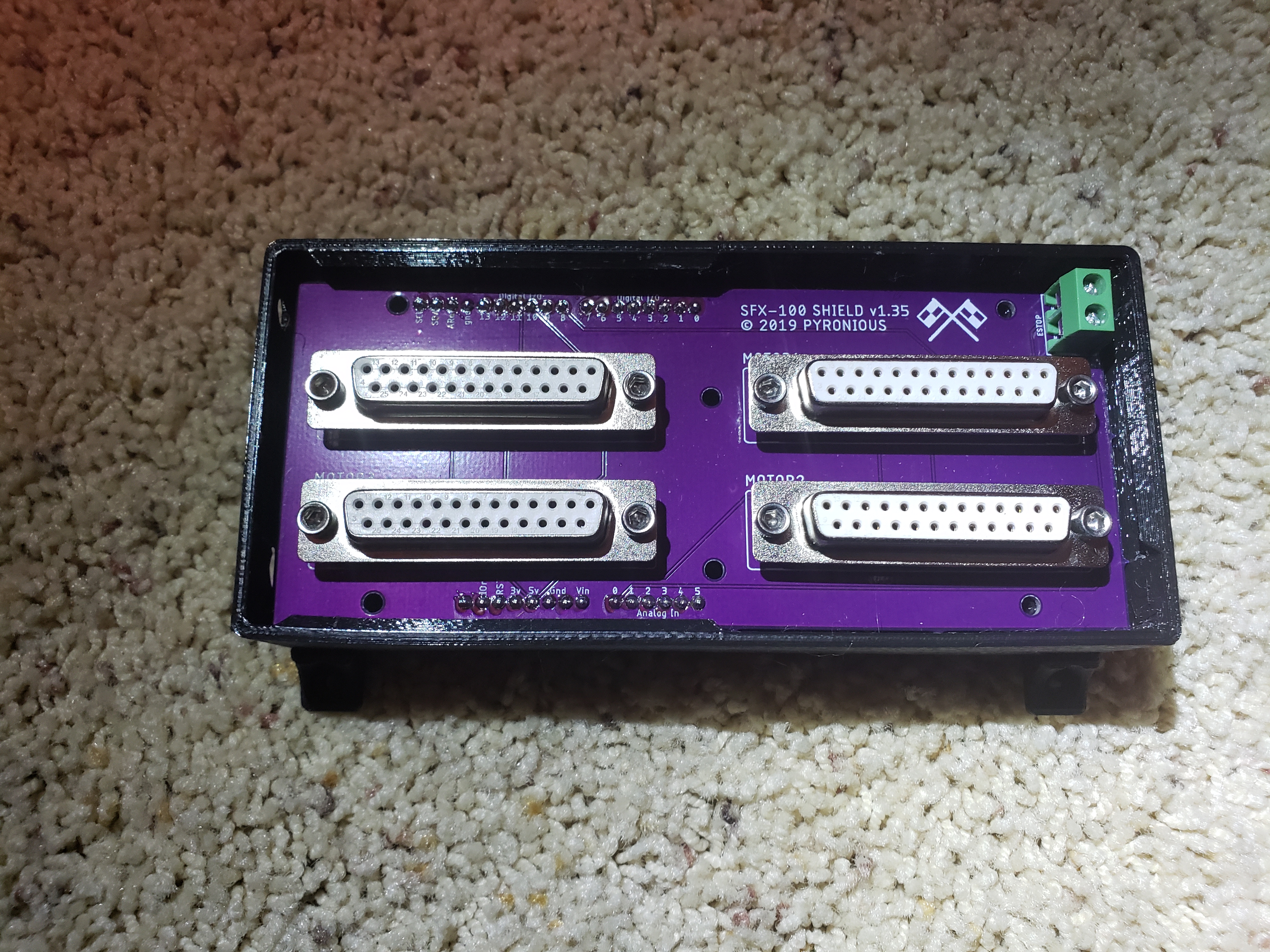
And the complete breakout board attached to Arduino Leonardo:
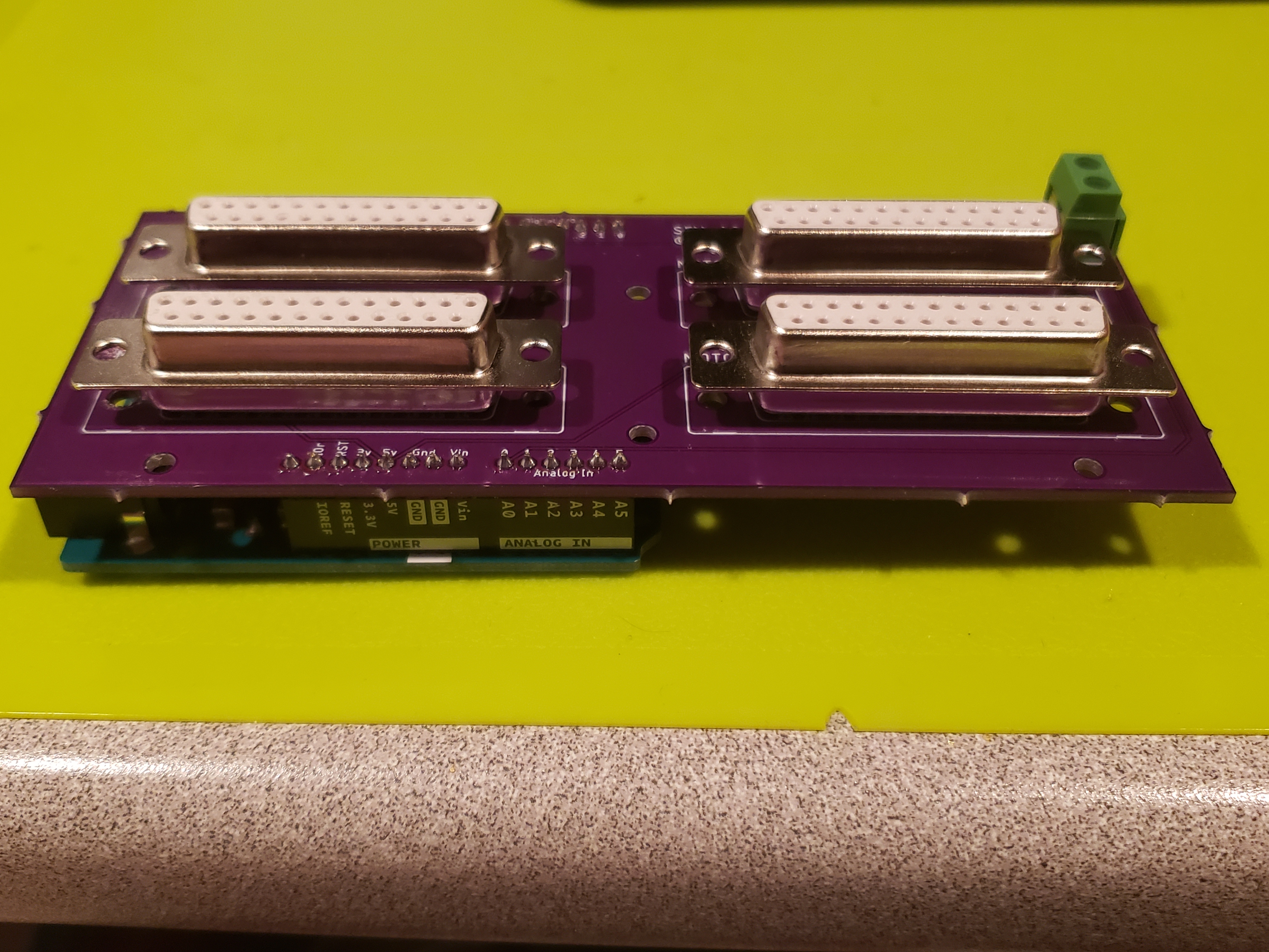

I didn’t have correct stand-offs at hand to screw the DB25 connectors to PCB, but considering that all the wiring will be put into a cabinet, I don’t anticipate for that to be a problem (the cables won’t move over time).
At this point you can connect the Arduino to your PC and flash it – use Simfeedback software to do so:
https://opensfx.com/simfeedback-setup-and-tuning/
Now to be able to test it, we need motors.
Wiring and testing the motors
Once the motors arrive, you’ll find that a single set consists of 3 components: motor, controller, power + data cables:
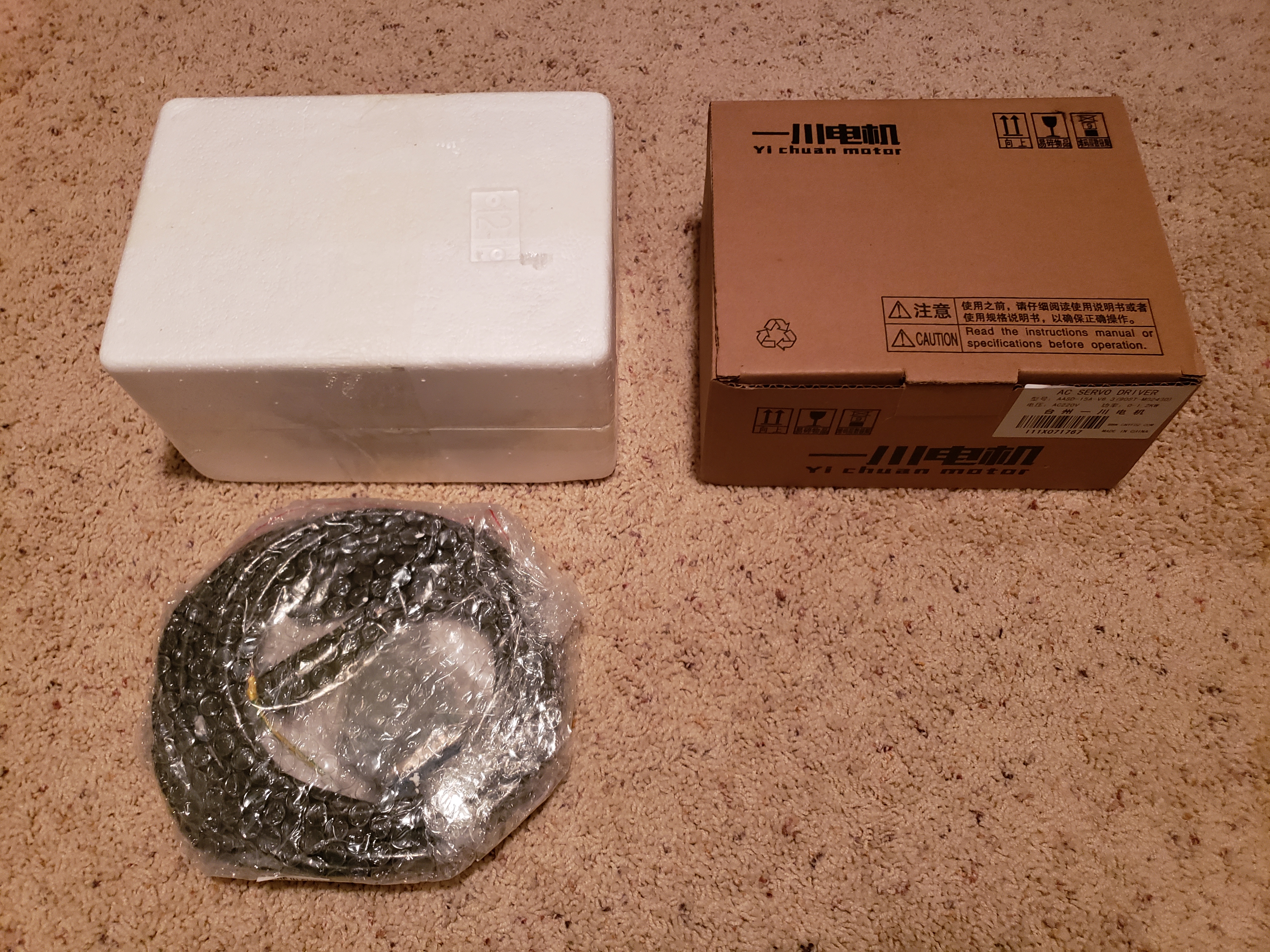
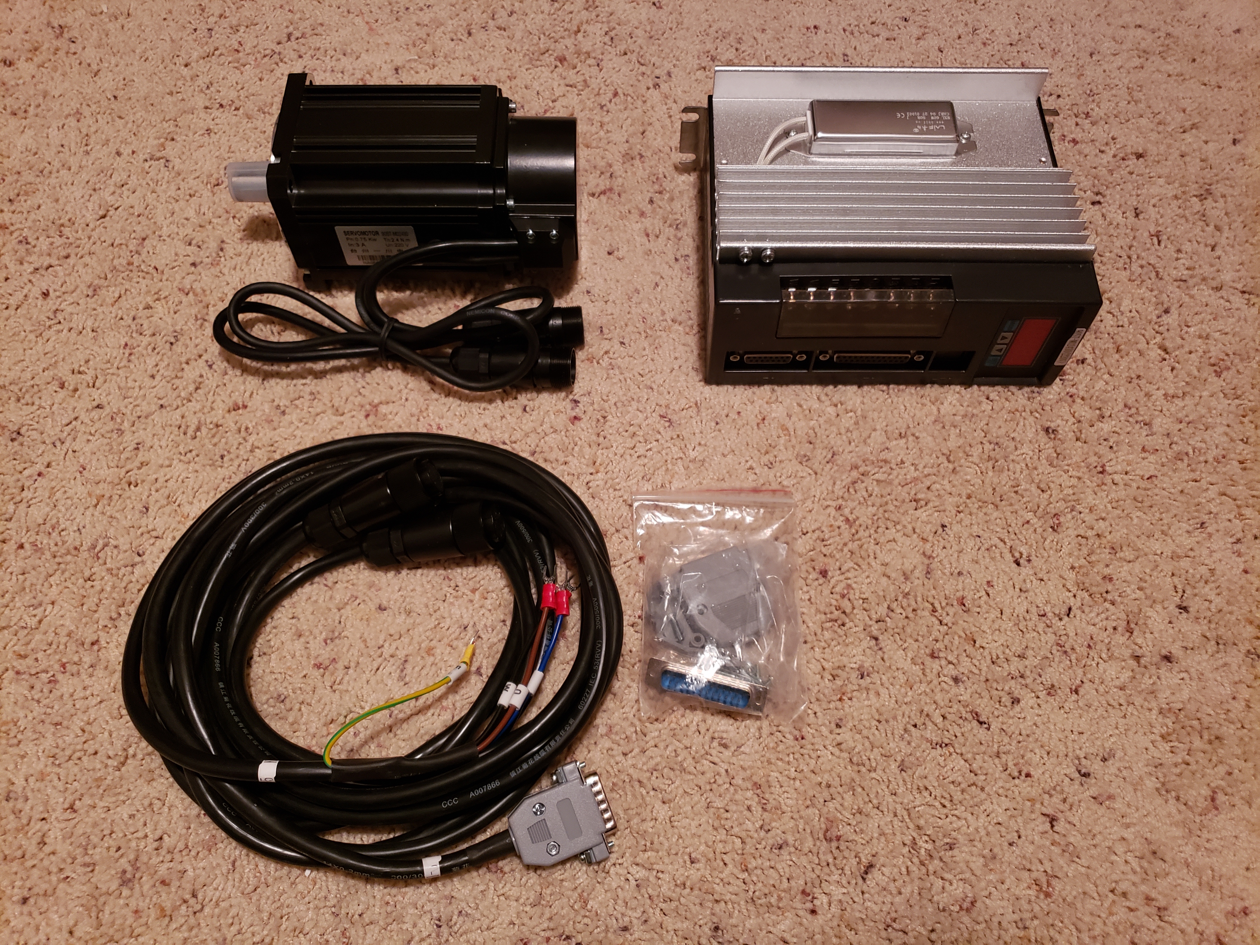
The connectors between power and data cables for motors are quite unique – as in, not really used in retail applications, which is another indication that we’re dealing with a commercial/industrial type of hardware 😉
To attach them, start screwing both pieces together, and when you encounter resistance, push the 2 halves towards each other, then continue screwing. Repeat until they can’t be pushed closer together. If you have to separate them, do the opposite – loosen thread as much as you can, then pull them apart and repeat until success.

Now comes first thing that we should approach with caution – wiring of the power for motors. We’ll be dealing with higher voltage (depending on where you live, 220V or 110V).
Check all the connections 2, 3 or 4 times before plugging it into a wall outlet.
Always stay clear from the non-isolated connections.
If you don’t feel comfortable splicing the power cables, you can purchase separate power cord for each controller (4 total, 3ft length each would be sufficient) and a power strip to plug them all into. You will still need to strip and crimp their ends, but there’s less of that thus less room for error. I chose the more compact solution (splicing and daisy-chaining), but both will work equally well.
We’ll be splicing the long power cord (see bill of materials) into 3 smaller pieces to daisy chain between motor controllers (controller #1 to #2, #2 to #3, and #3 to #4).
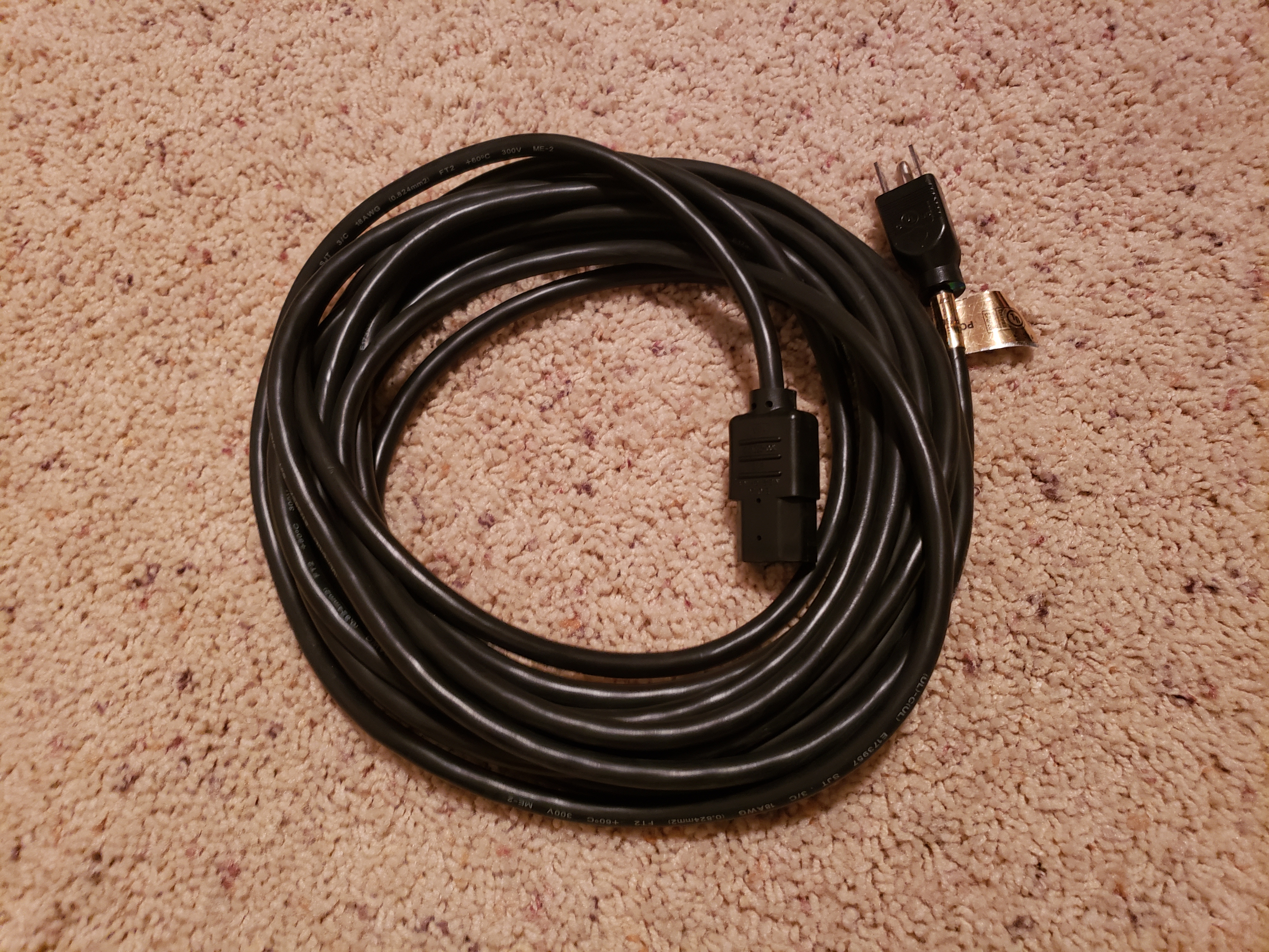
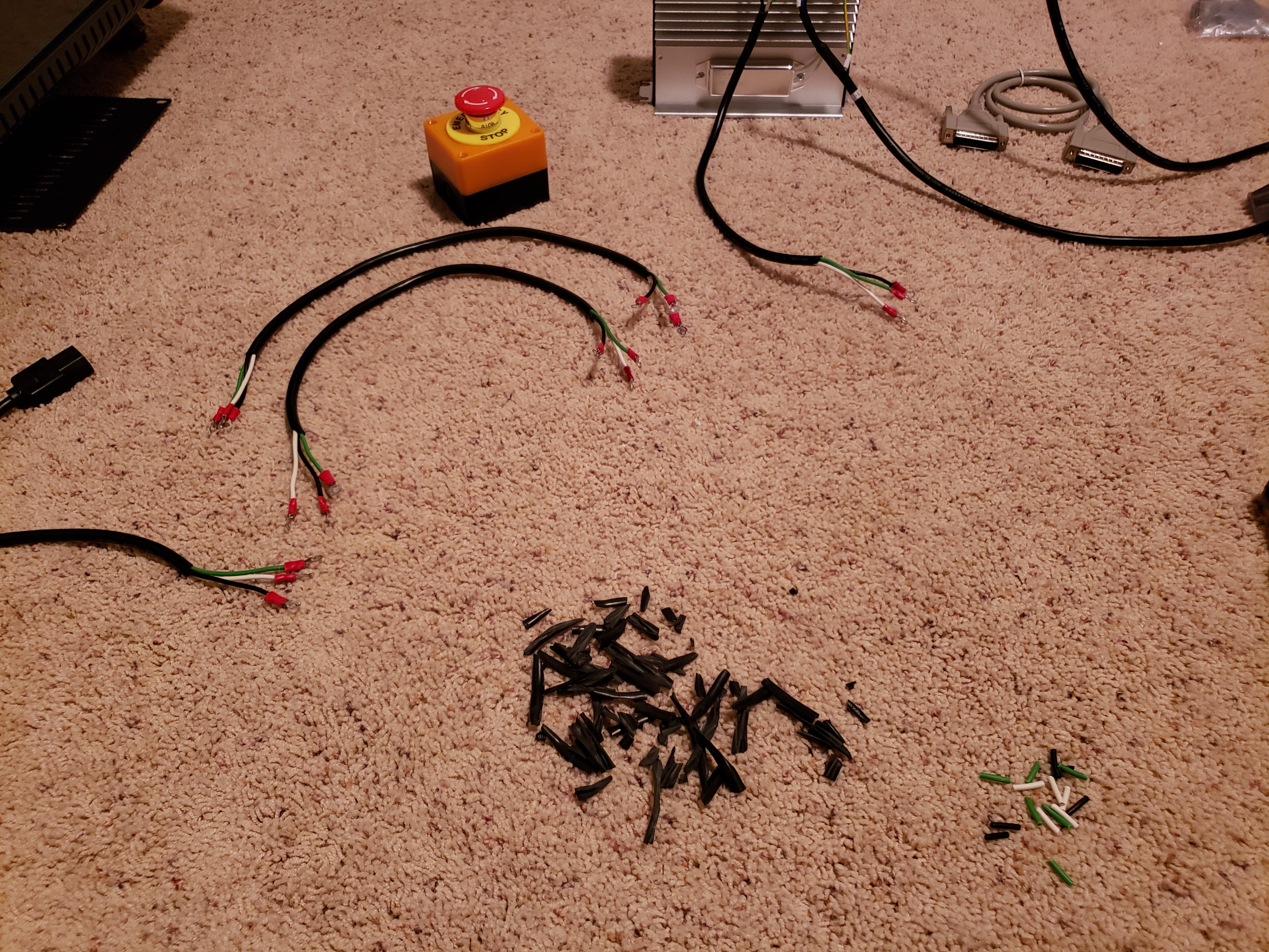
Cut the female plug away (leaving the wall socket side plug untouched), then cut 3 pieces off of the cord, approximately 22″ – 24″ long:
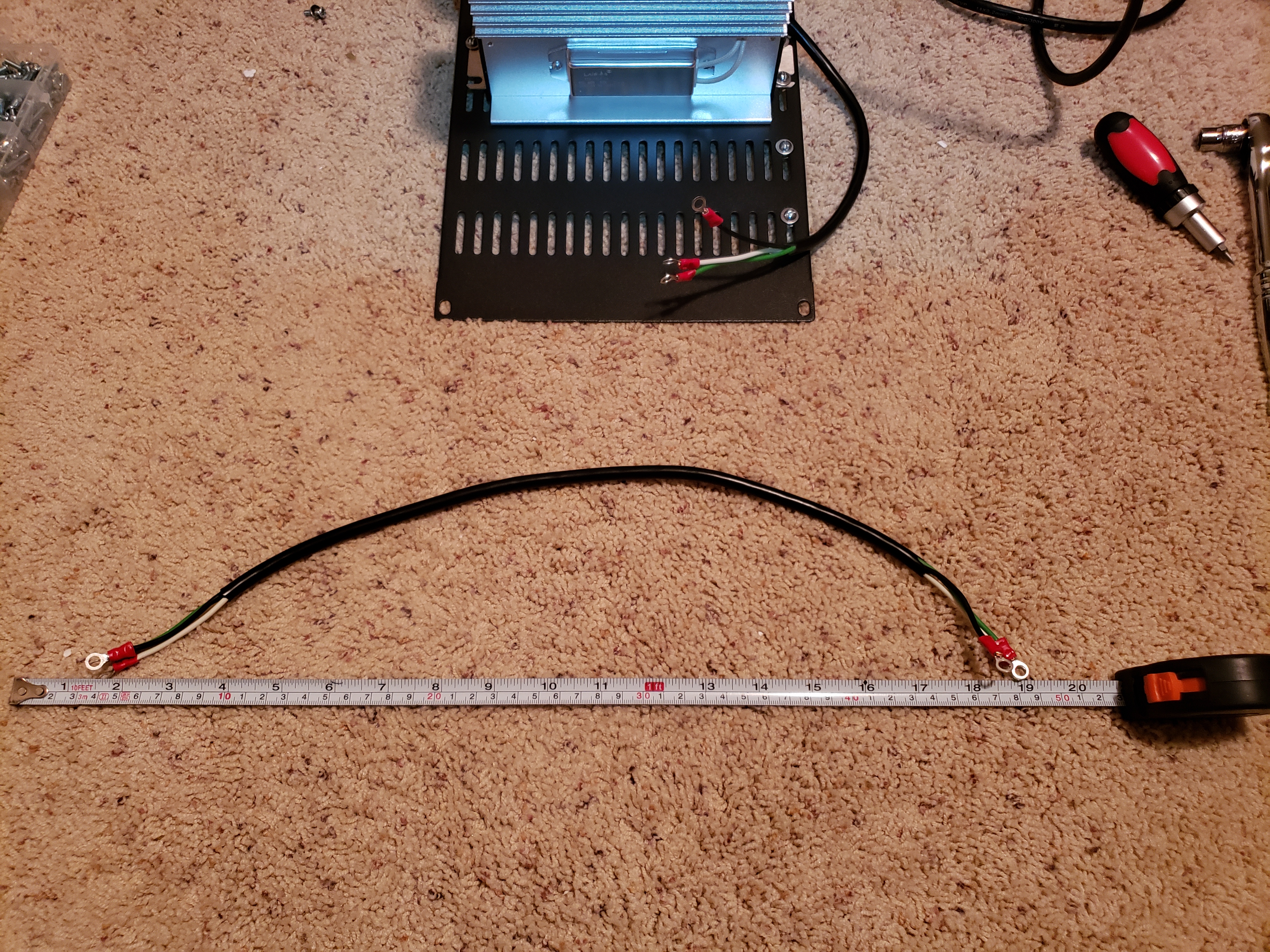
Next, strip the ends of each cable. Removing the external layer of insulation (the one encapsulating all wires) can be a bit tedious process. What I found to work well is making incision at the end using e.g. flush cutters and then pulling on those pieces with 2 sets of pliers to peel it like a banana 🙂
We want to have about 3″ of exposed wires after removing external insulation, and then finally strip their ends:
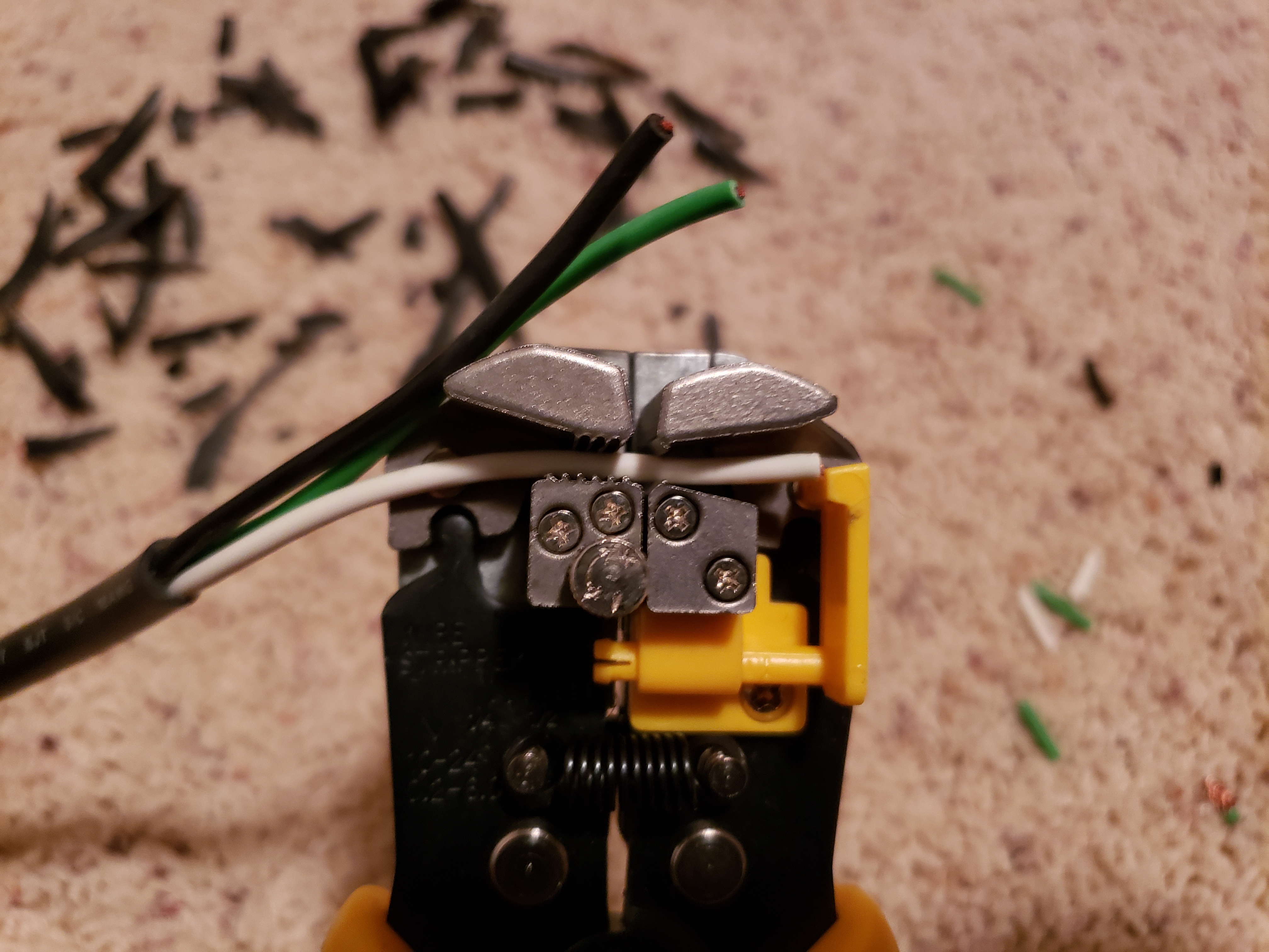
Check out the bill of materials if you don’t have a wire stripping tool already.
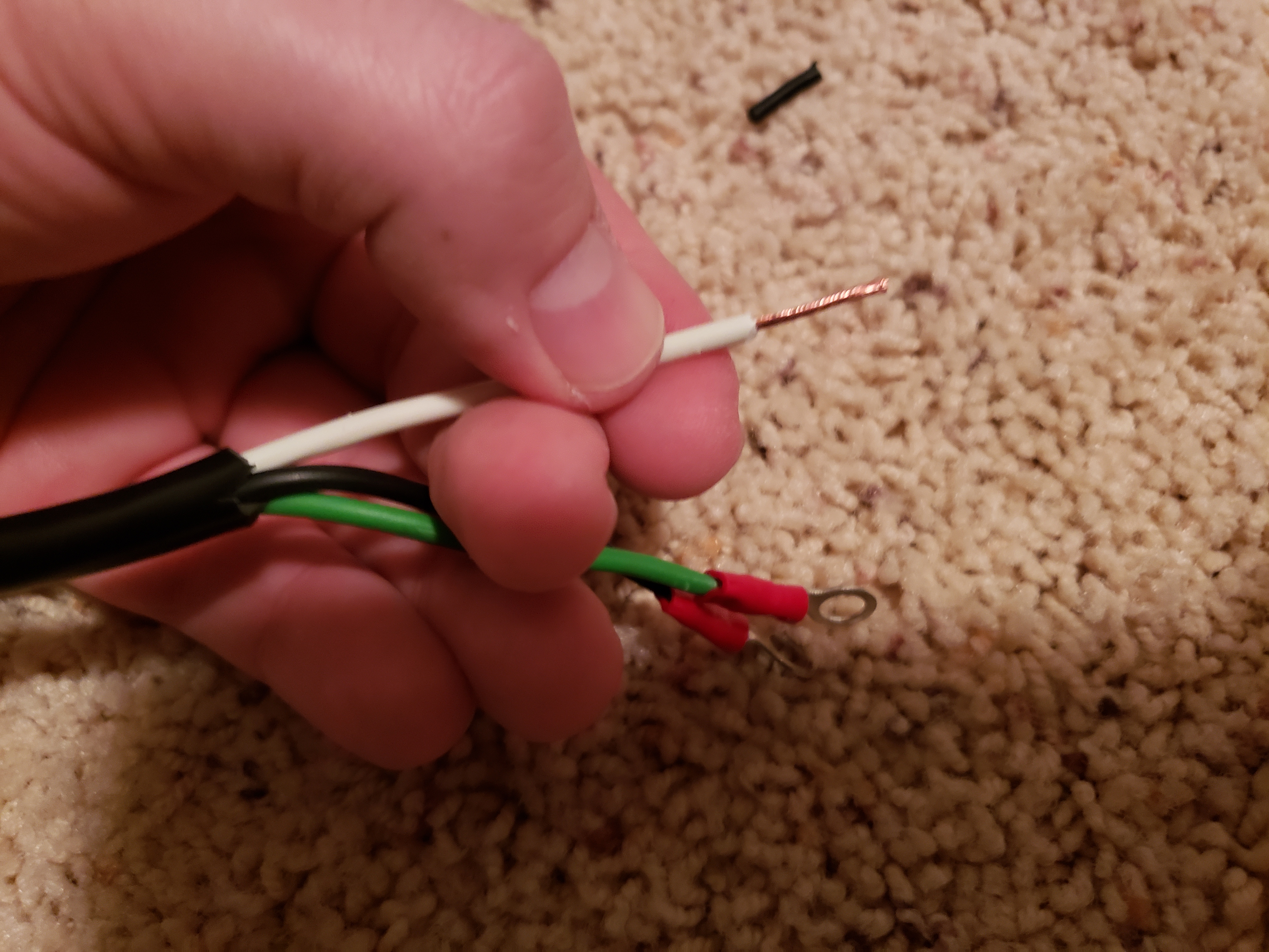
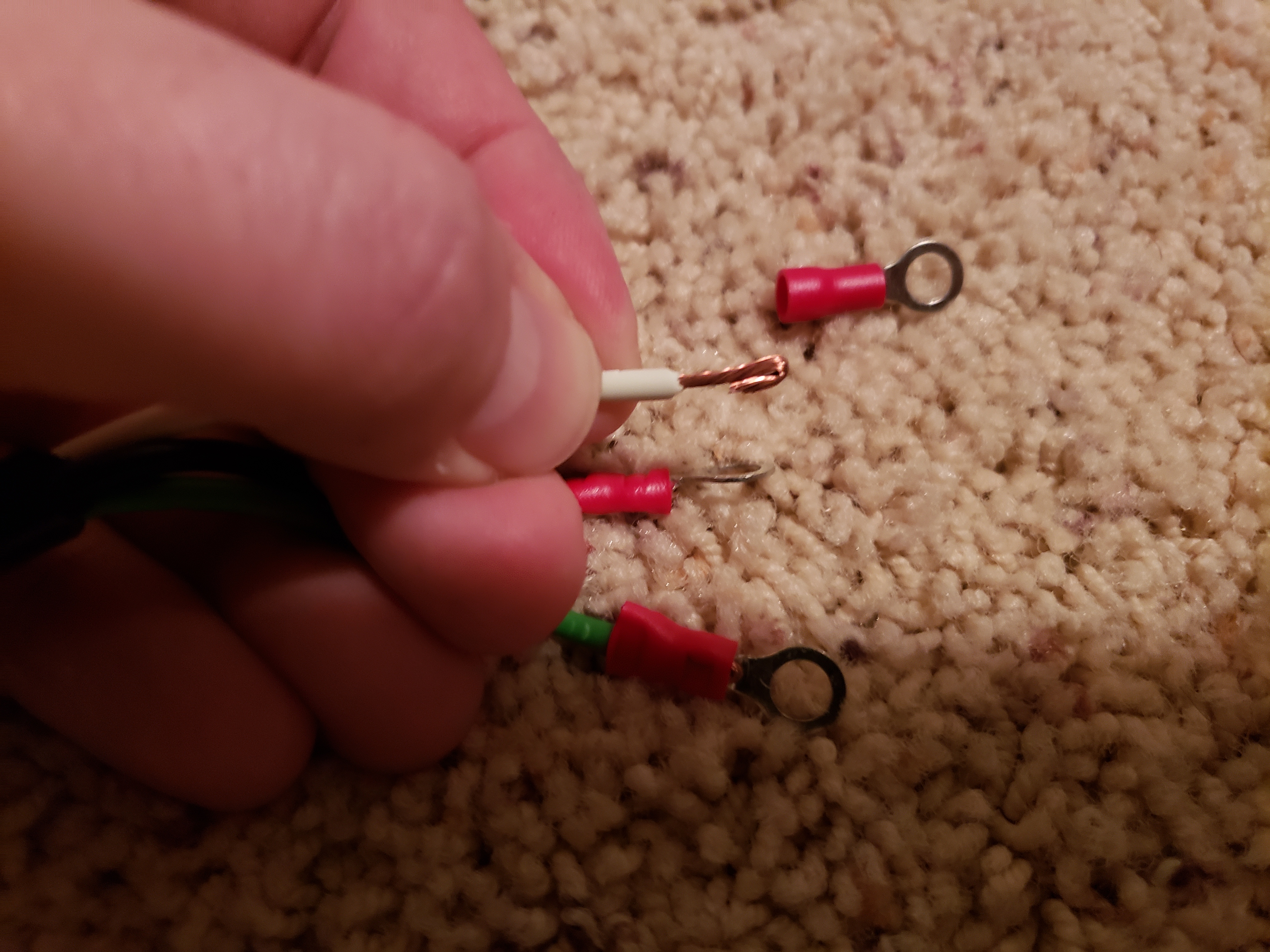
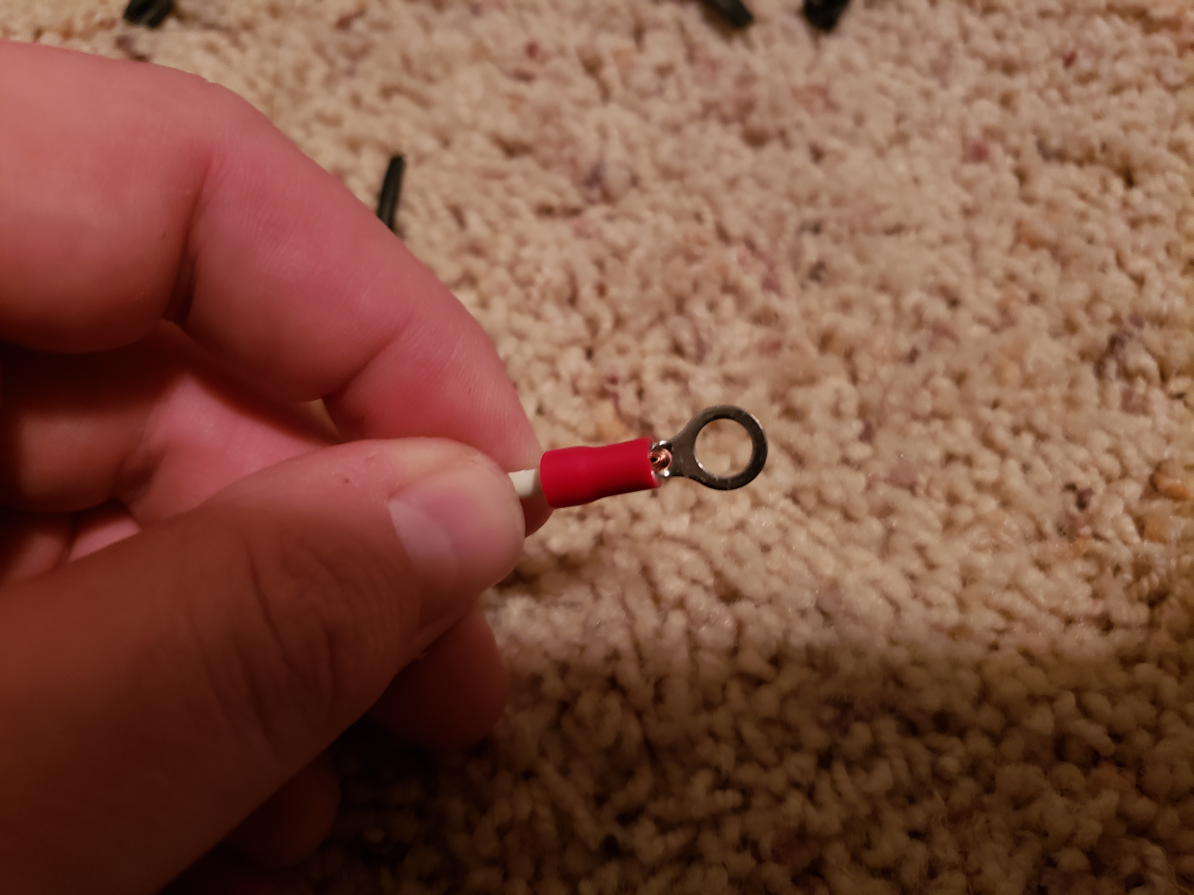
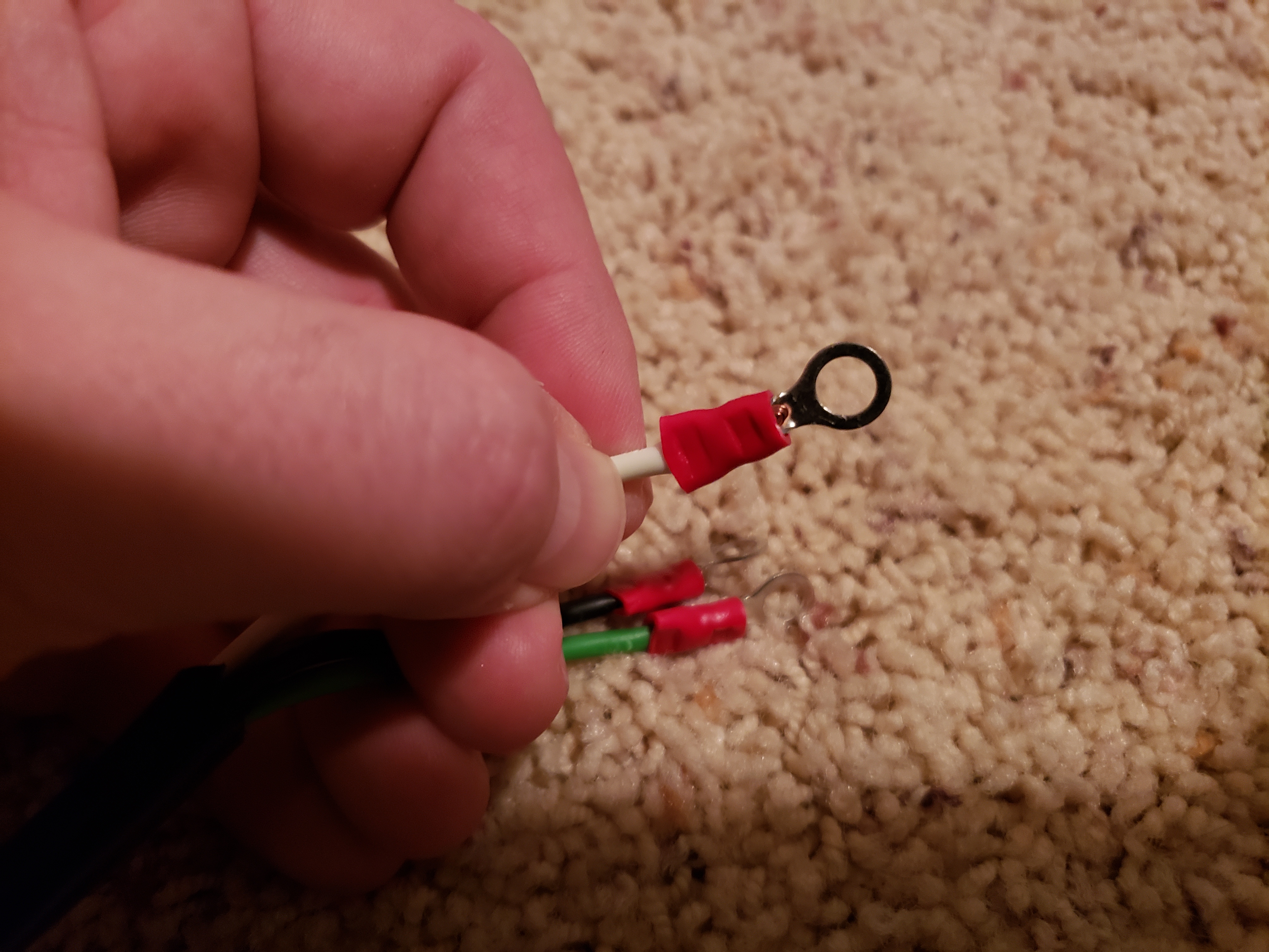
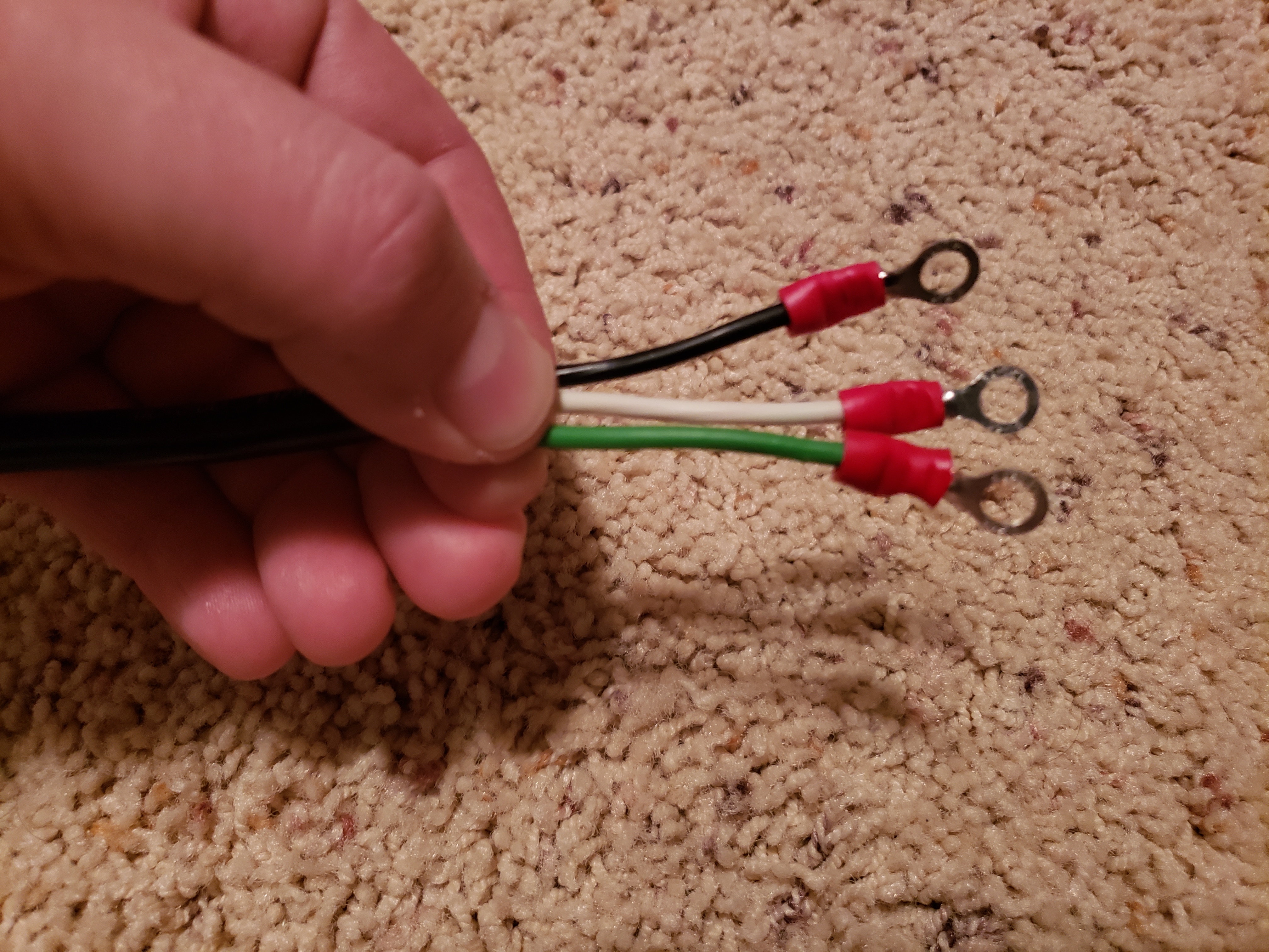
Now crimp the connectors – I like to make a small loop (fold?) at the end of each wire before pushing it into connector, to have larger surface for crimping. After crimping each one, tug on it to make sure it’s secure and doesn’t come off:
And when you’re done, don’t forget to clean the mess 🙂 I was doing it on the floor, and had to vacuum some small shavings of the insulation afterwards:
With all the wires ready, it’s time to connect it all together.
Here’s a quick reference for the wiring of a plug in North America. Be sure to double-check the wiring in your region, this is a place where we don’t want any mistakes:

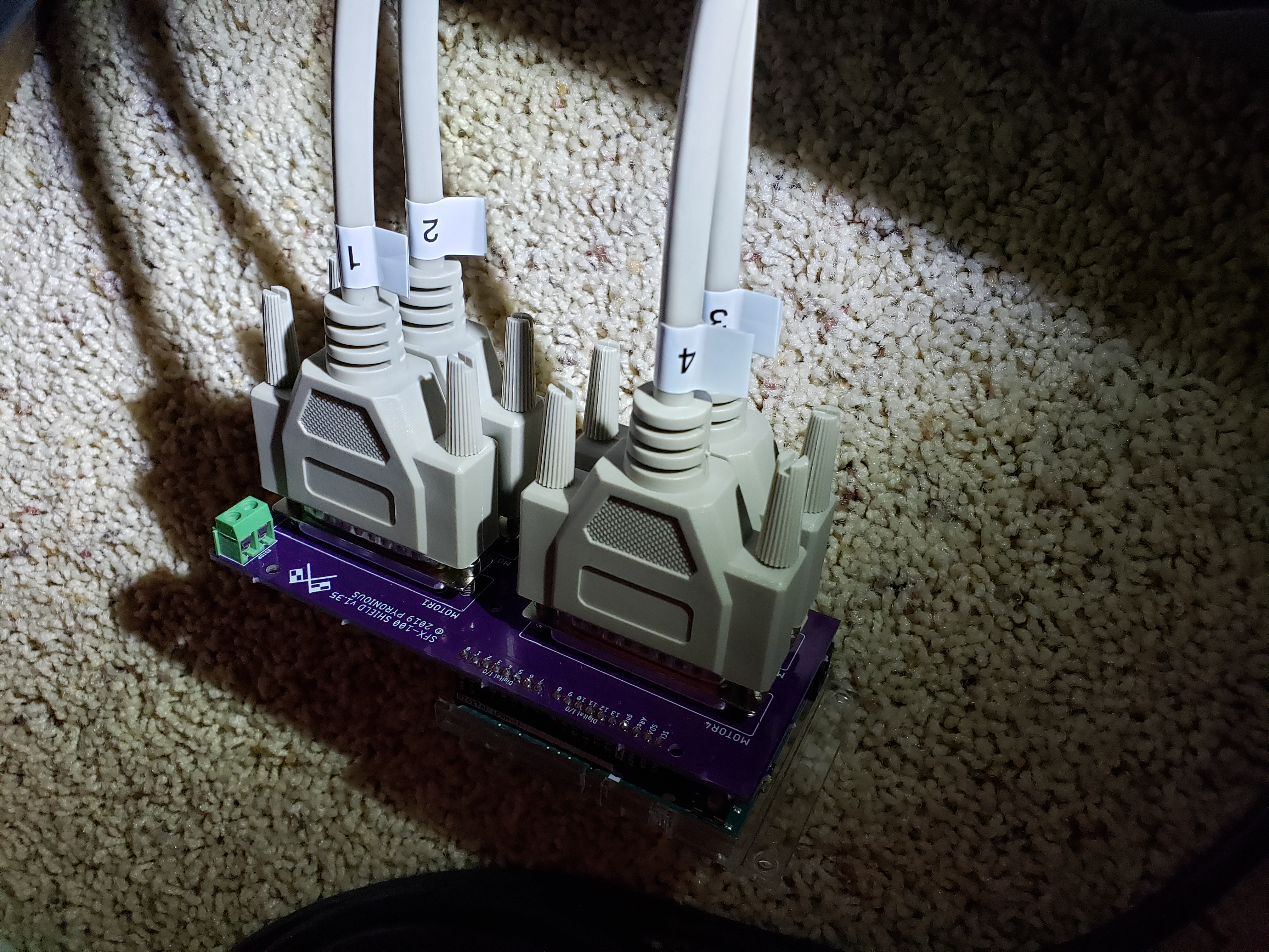
And here’s final wiring for a single motor controller:
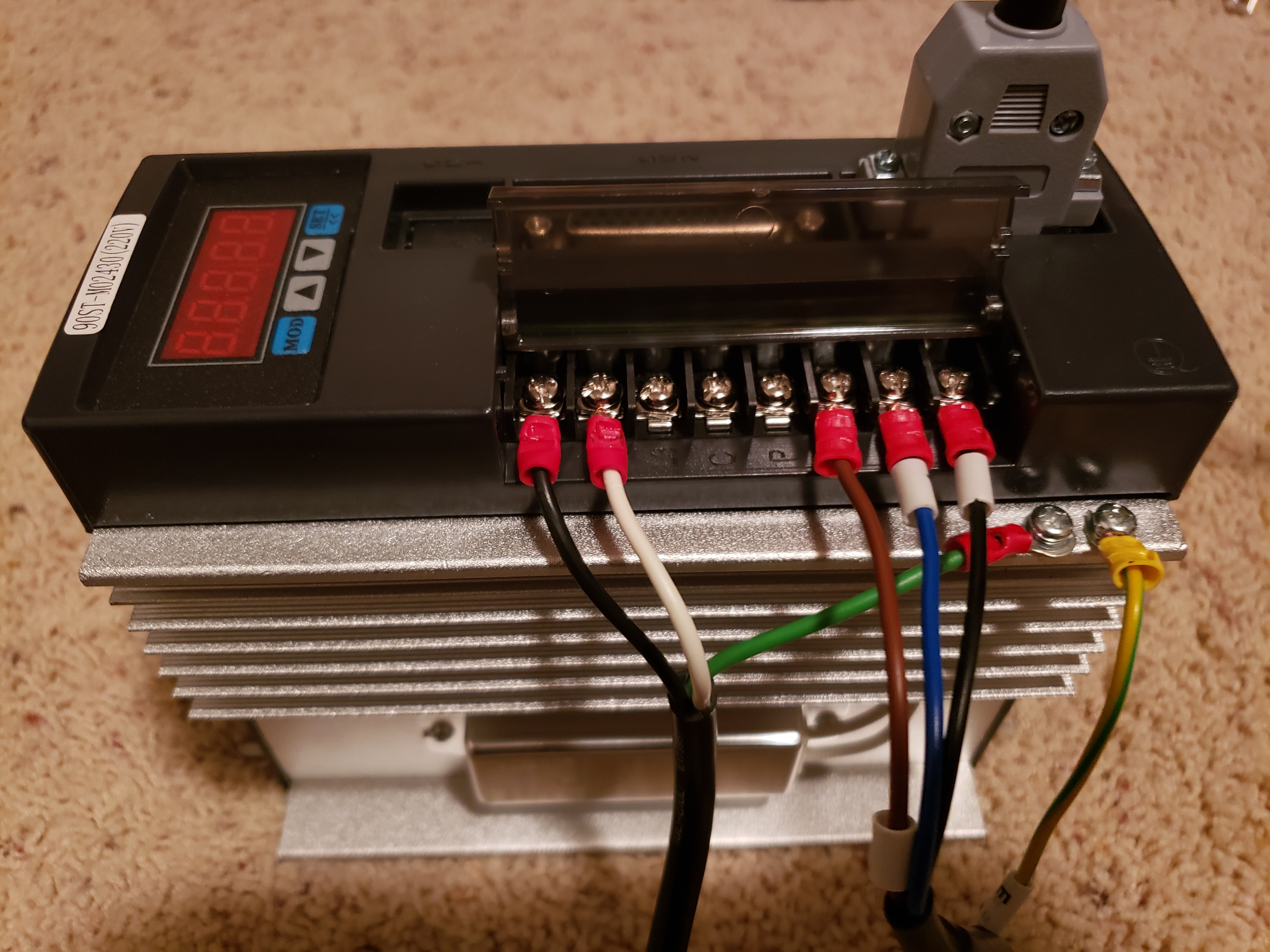
Note that for all except the last controller, the 3 power connections (white, black and green wires) will be doubled for each screw, since we’re daisy-chaining them.
And you can see on the last photo above that connecting the data (encoder) cables to controllers is a breeze – they come with labels (u, w, v) to indicate their connections.
Powering the motors on 110V
Read if you live in US, skip if you’re in Europe 🙂
The servos are designed to work off of 220V. However, we don’t get that much from regular wall sockets in US. There are few solutions to this problem:
- have a dedicated 220V line pulled to your sim racing room by an electrician,
- purchase a voltage step-up converter (~$150-$250),
- configure the servos to just work on 110V 🙂
I ordered voltage converter with the first batch of parts for the build, but after finding out how to power them from 110V, I returned it unused/unopened.
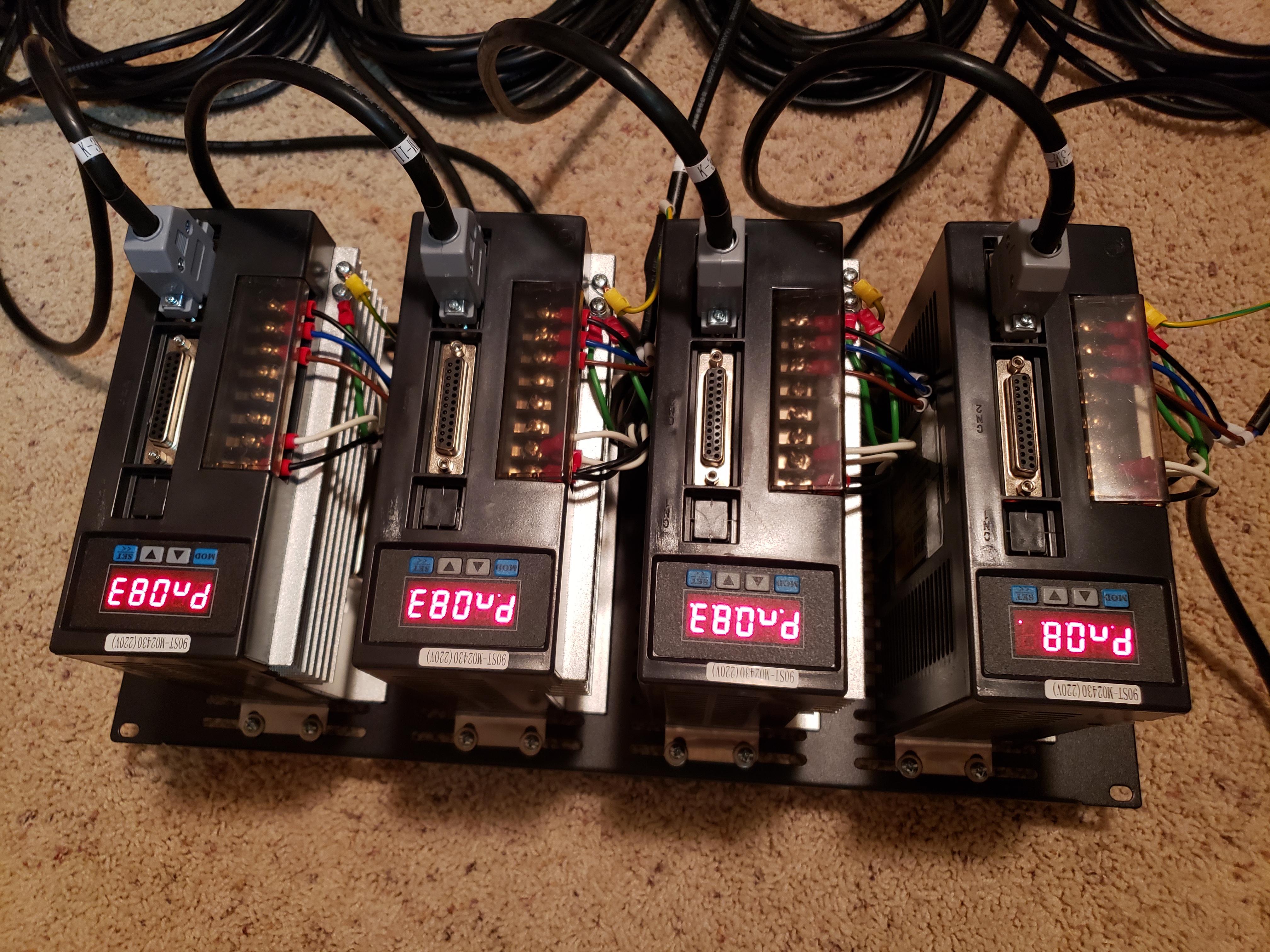
Turns out, there’s a setting in the controller for “under-voltage alarm”. It’s set to 200V by default, but overriding it by setting to 100V, we can enable the servos to work without noticeable loss of performance.
Changing under-voltage alarm threshold:
- Navigate to function Pn83
- Confirm the selection
- Change the value to 100 (yes, “100” – less than 110V, since this is the alarm threshold)
- Confirm the selection
The motors will now run on 110V.
Also check out this great video outlining the process:
Video credit: Thanos (aka tronicgr)
Now, one additional thing we now have to do – since we powered the motors from 110V even before changing the alarm threshold, the alarm has been activated. Some functions available through the controllers (including “jog” function) will not work until the alarm status is reset.
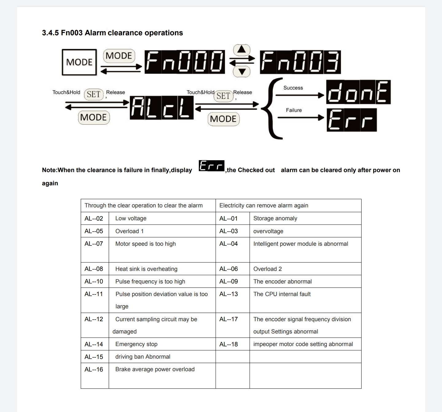
Clearing all alarms (including under-voltage alarm):
- Navigate to function Fn003
- Navigate to mode ALCL
- Confirm the selection – all alarms have now been cleared
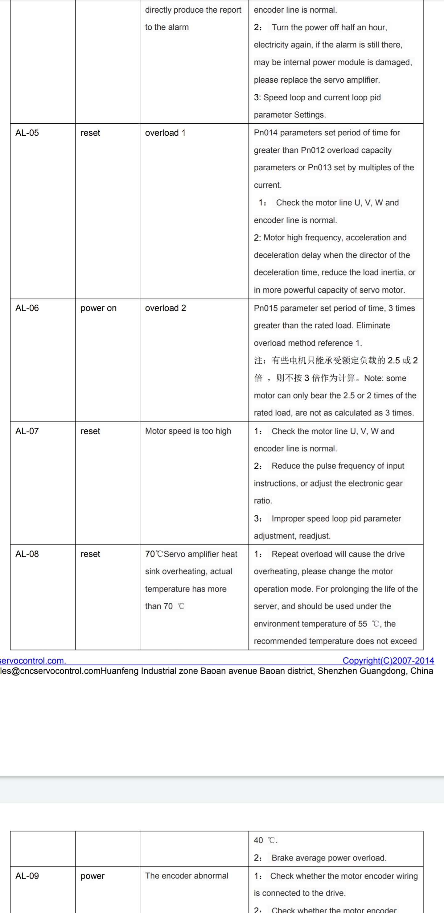
Here are relevant pages from the manual, describing clearing the alarm as well as alarm codes:
Configuring the motors
Before we can start it up and use/test, we need to configure few additional parameters of the controllers accordingly. Please refer to the SFX-100 documentation to see the list of required parameters and their values. Don’t change any other parameters, unless you’re sure you know what they do.
Configuration settings are available here:
https://opensfx.com/testing-and-configuring-servo-drives/
Copied here for reference:
P8 = 300
P9 = -300
P51 = 1200 (max 3000) – max RPM, start slow and then adjust as desired
P98 = 20 – Pulse Multiplier
P109 = 1 – smoothing (1 = fixed smoothing, 2 = s-shaped smoothing)
P110 = 30 – Smoothing Filter Time
P113 = 20 – Feedforward %
P114 = 10 – Feedforward Filter Time (ms)
P115 = 100 – Gain %
Refer to the servo manual for more information if needed.
Testing the motors (jog function)
Make sure that the motors are located on a solid surface – they will move when activated, and we wouldn’t want for them to fall off a table or hit something.
To manually test the motors:
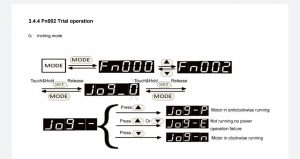
- Navigate to function Fn002
- Navigate to mode Jog_0
- Press up or down arrow to turn the motor shaft
- The display will show Jog_P when moving counter-clockwise, and Jog_N when moving clockwise
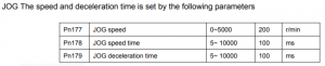
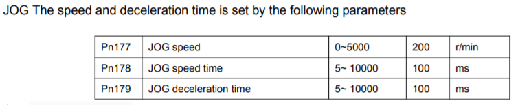
- The speed of Jog function can be configured using Pn177, but it’s not really necessary. Here’s a screenshot from the manual with relevant settings, for a quick reference:
- If you’re using the jog function with fully assembled actuators, the up arrow will correspond with the motion of the rig upwards, and down: downwards
Warning: when using the jog function with fully assembled actuators, make sure not to over-extend them. Doing so will lead to ball nut falling off of the screw. It’s quite annoying issue to fix. If you’re testing just the motors, before assembling actuators, you can use jog function without worry.
Here’s a relevant page from the manual:
You can also refer to the video provided on the official SFX-100 website:
Video credit: HoiHman
And my humble video from the first test of the actuators!
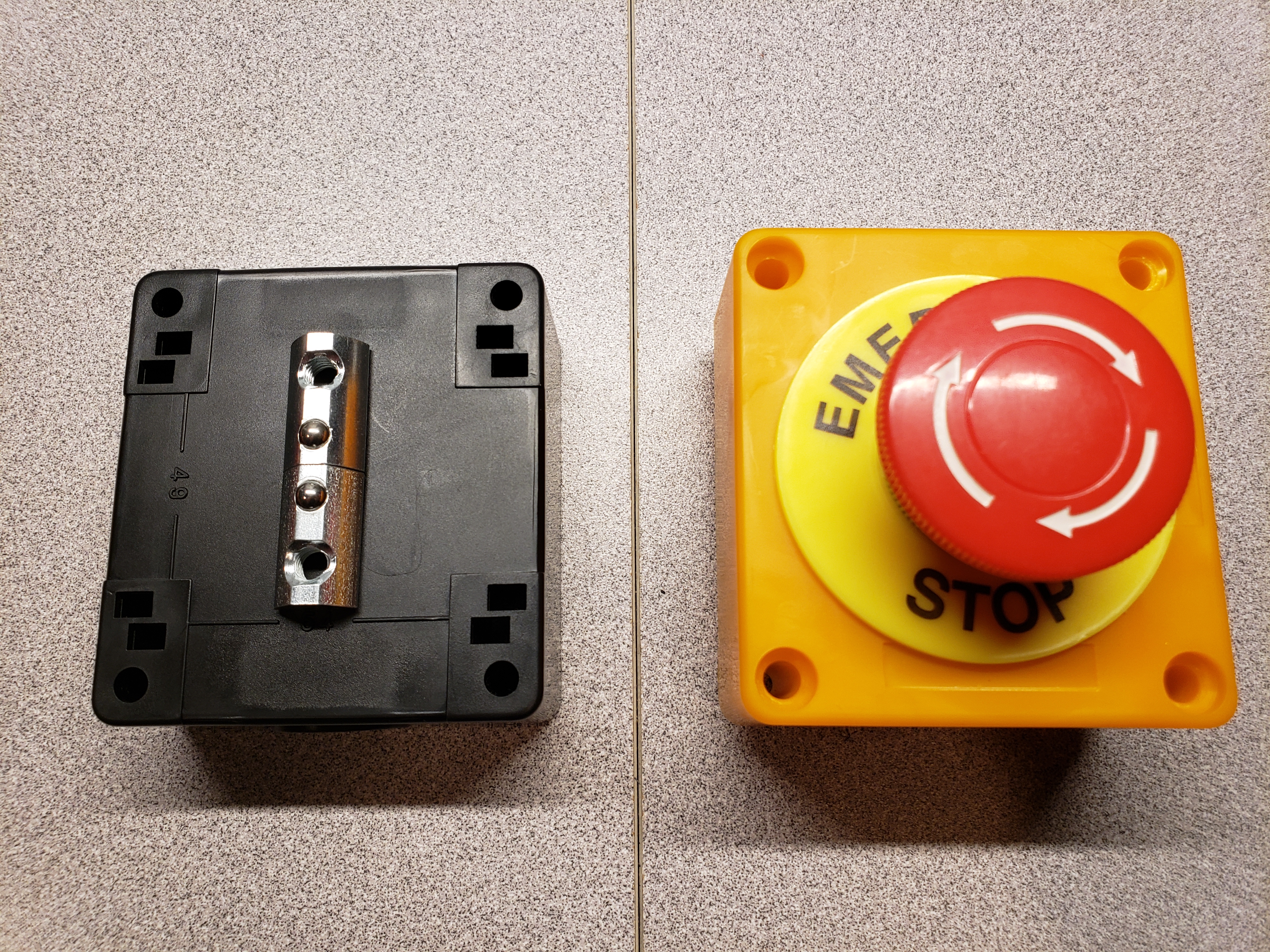
Emergency stop button
SFX-100 and SimFeedback support emergency stop button. It’s not a lot of work to add one, and it can come in handy. I highly recommend including it in your build. See bill of materials for link to the emergency stop button I’m using as well as the remaining parts.
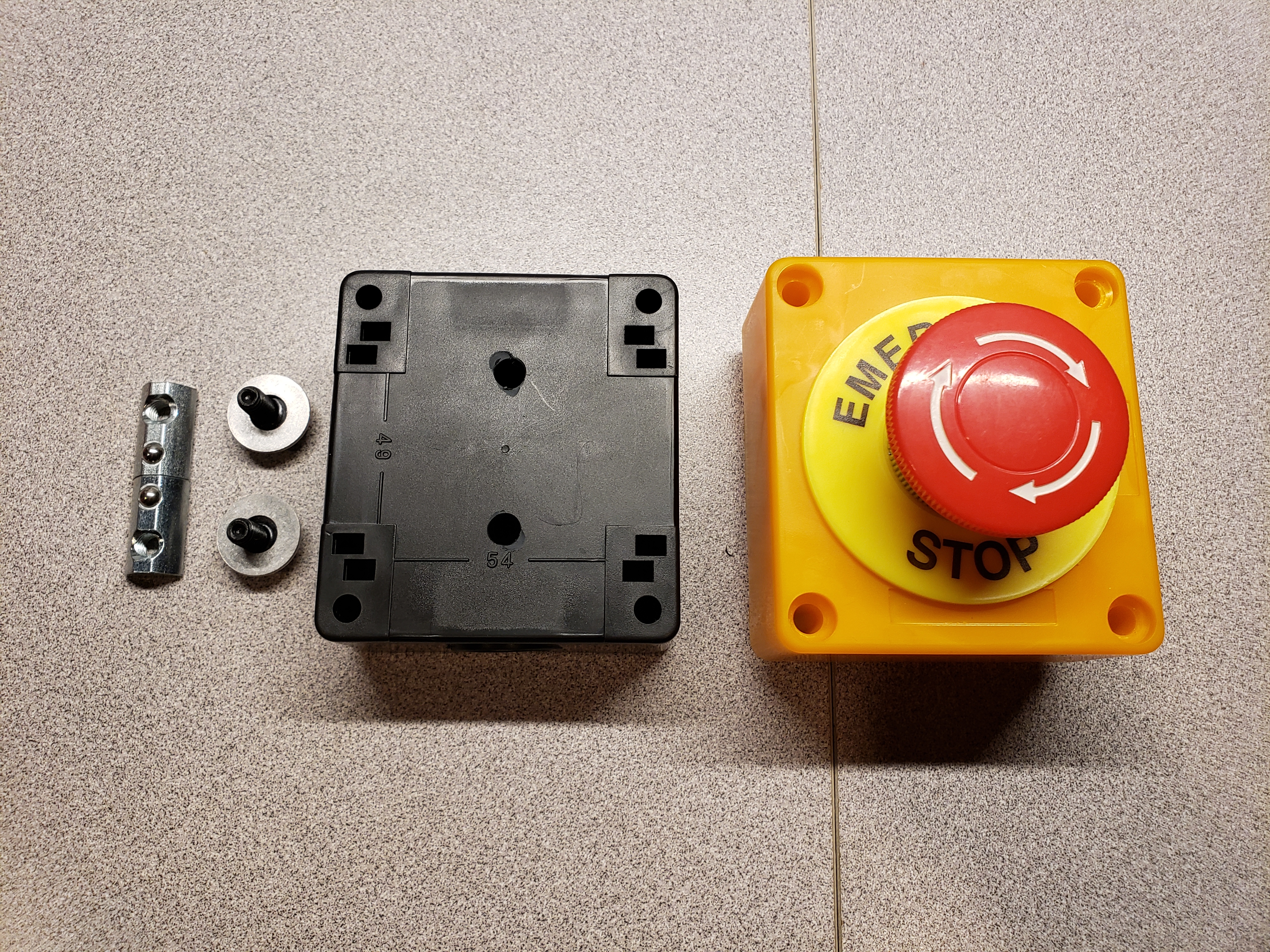
Before wiring, I positioned couple t-nuts on the base of emergency switch to see how it will be installed onto the rig, marked the holes and drilled them:
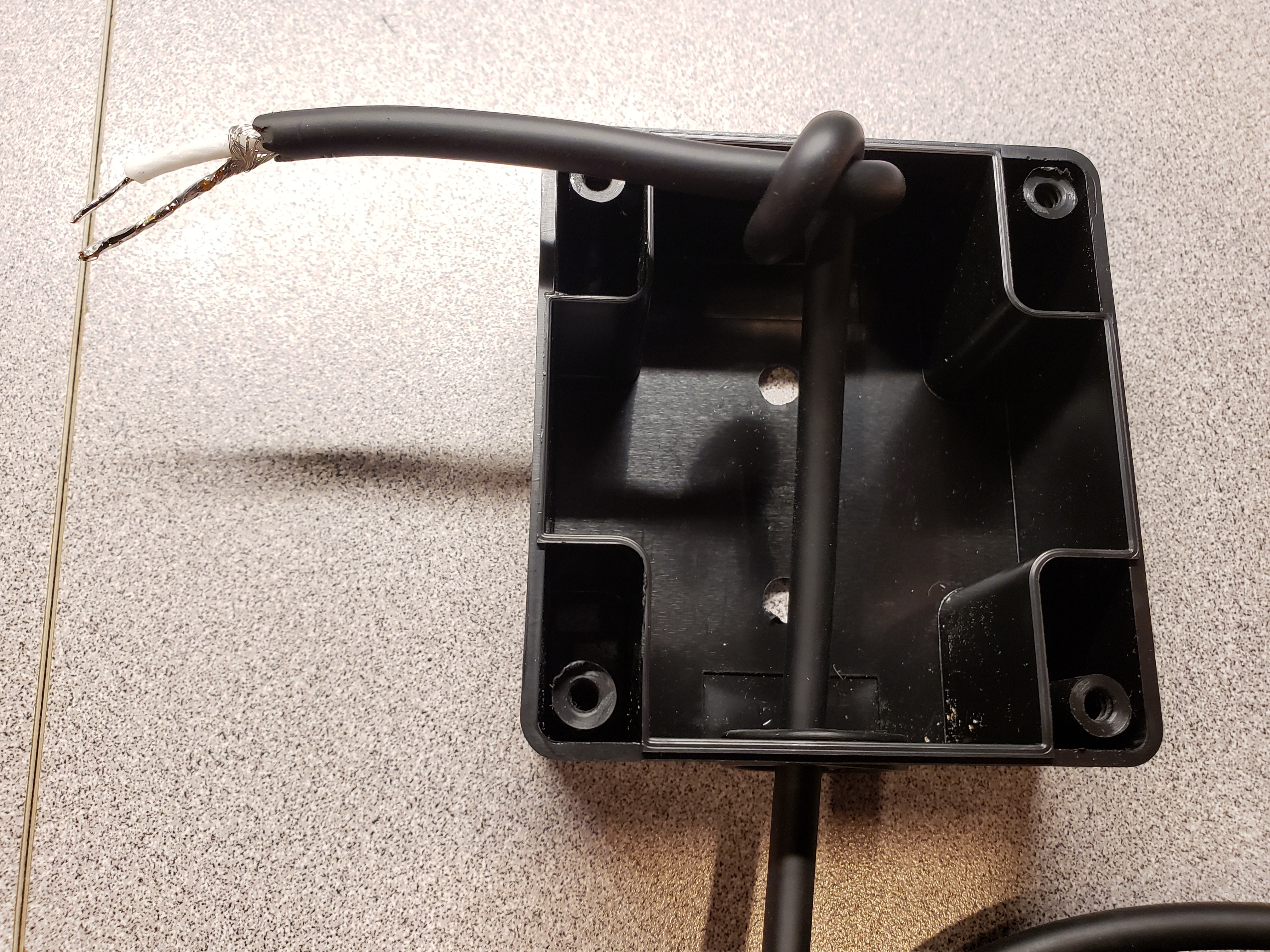
For wiring, I used an RCA cable, but any 2-conductor cable will do:
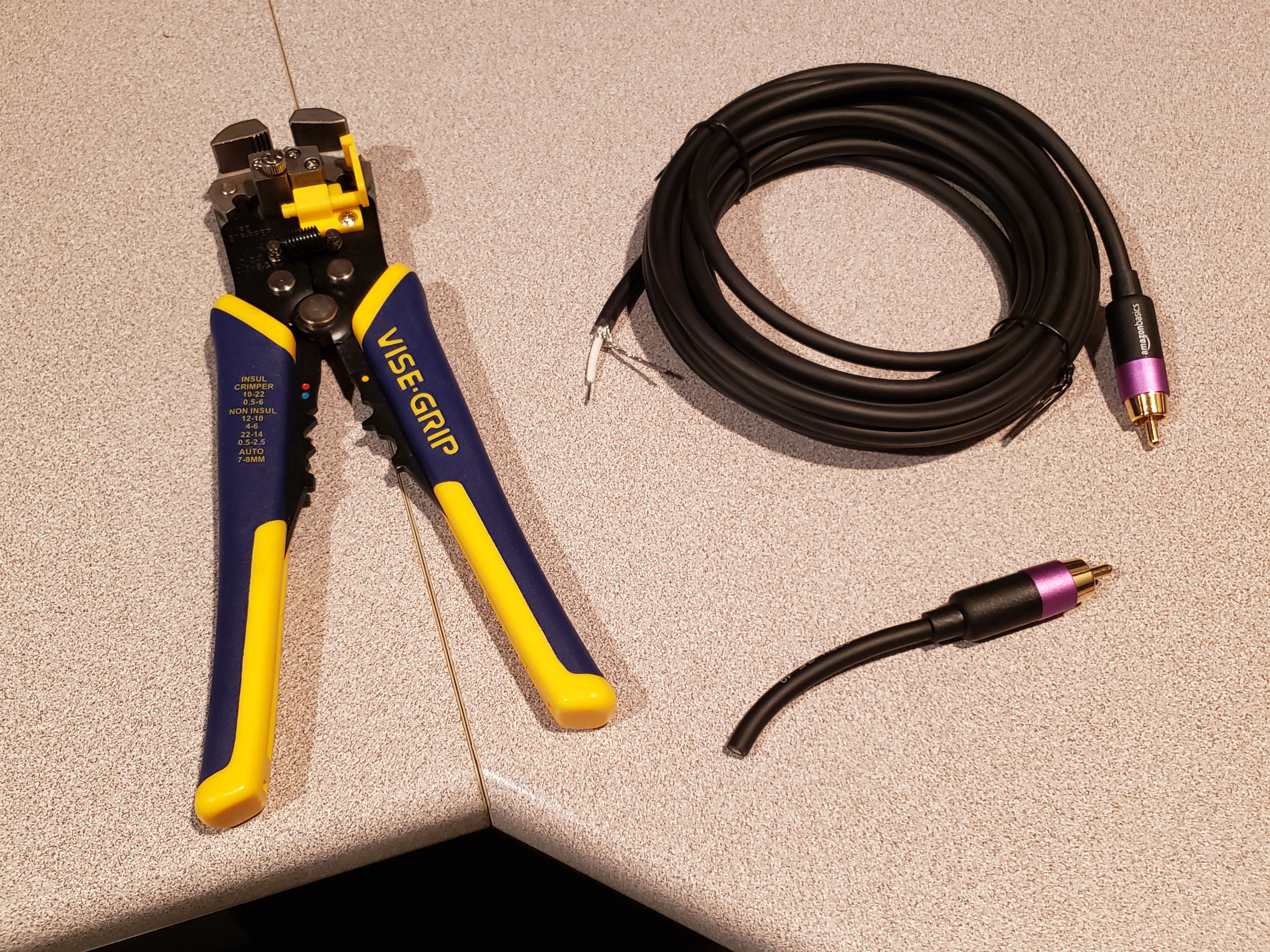
I added a bit of solder to the external shielding (which I’m using as one of the 2 conductors: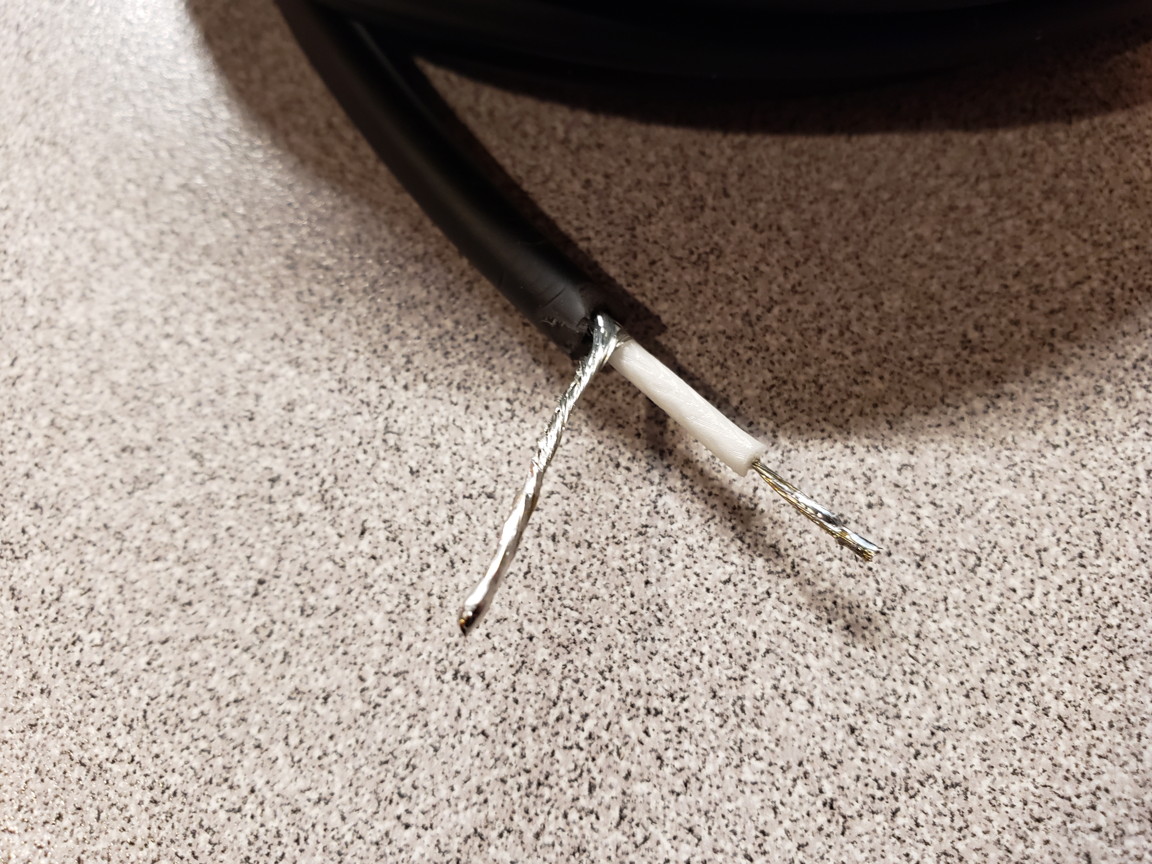
I also recommend adding strain-relief loop to the cable once we put it inside the button case. It will ensure that an accidental tug doesn’t pull it out.
Most emergency switches have 2 sides for connections: NO – normally open, circuit remains interrupted until the button is pressed, and NC – normally closed, pressing the button interrupts the circuit. We need to wire the cable to the NC side (normally closed).

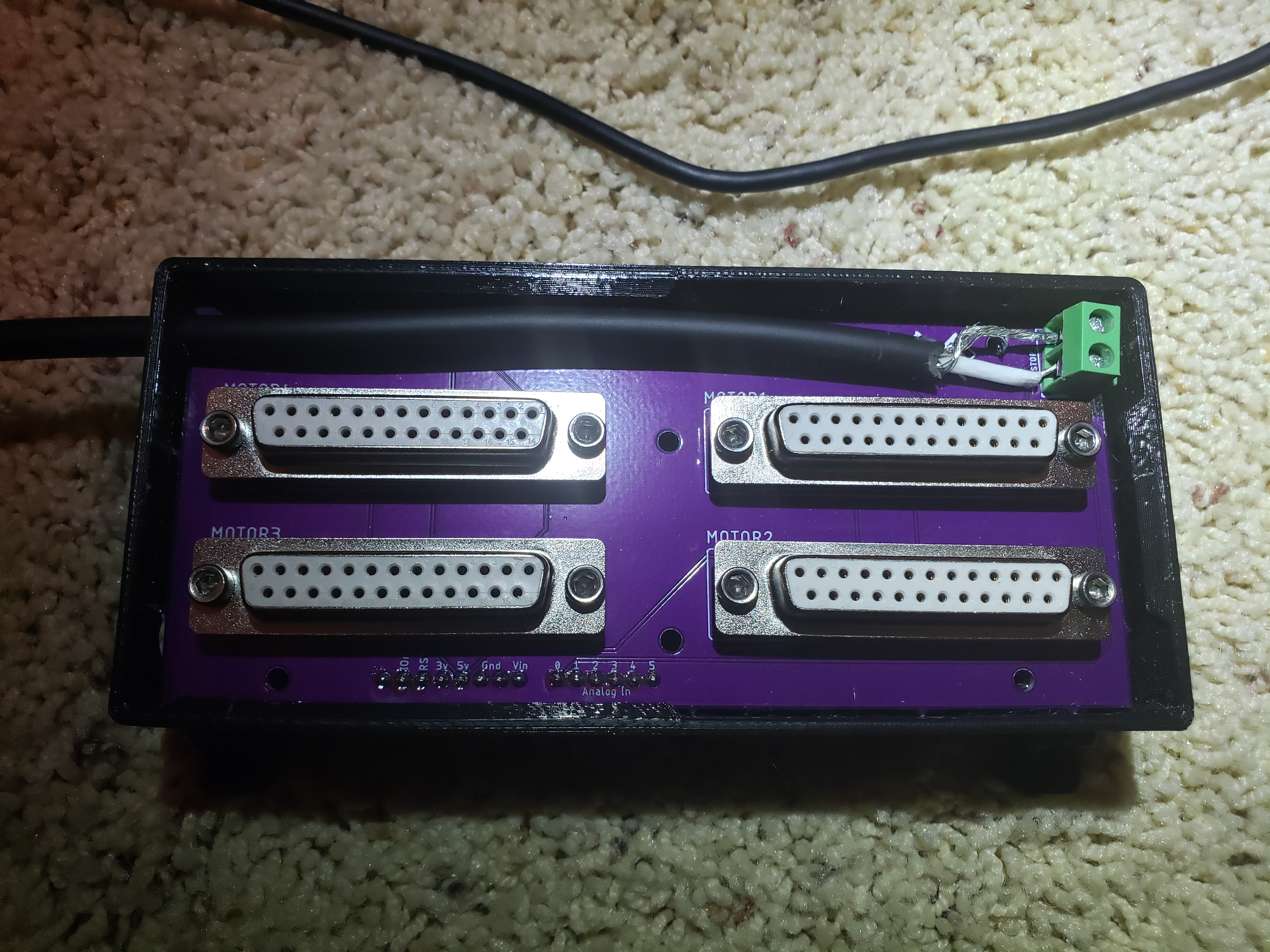
The other end of the cable needs to be plugged into the green connector on the breakout board which we soldered previously.
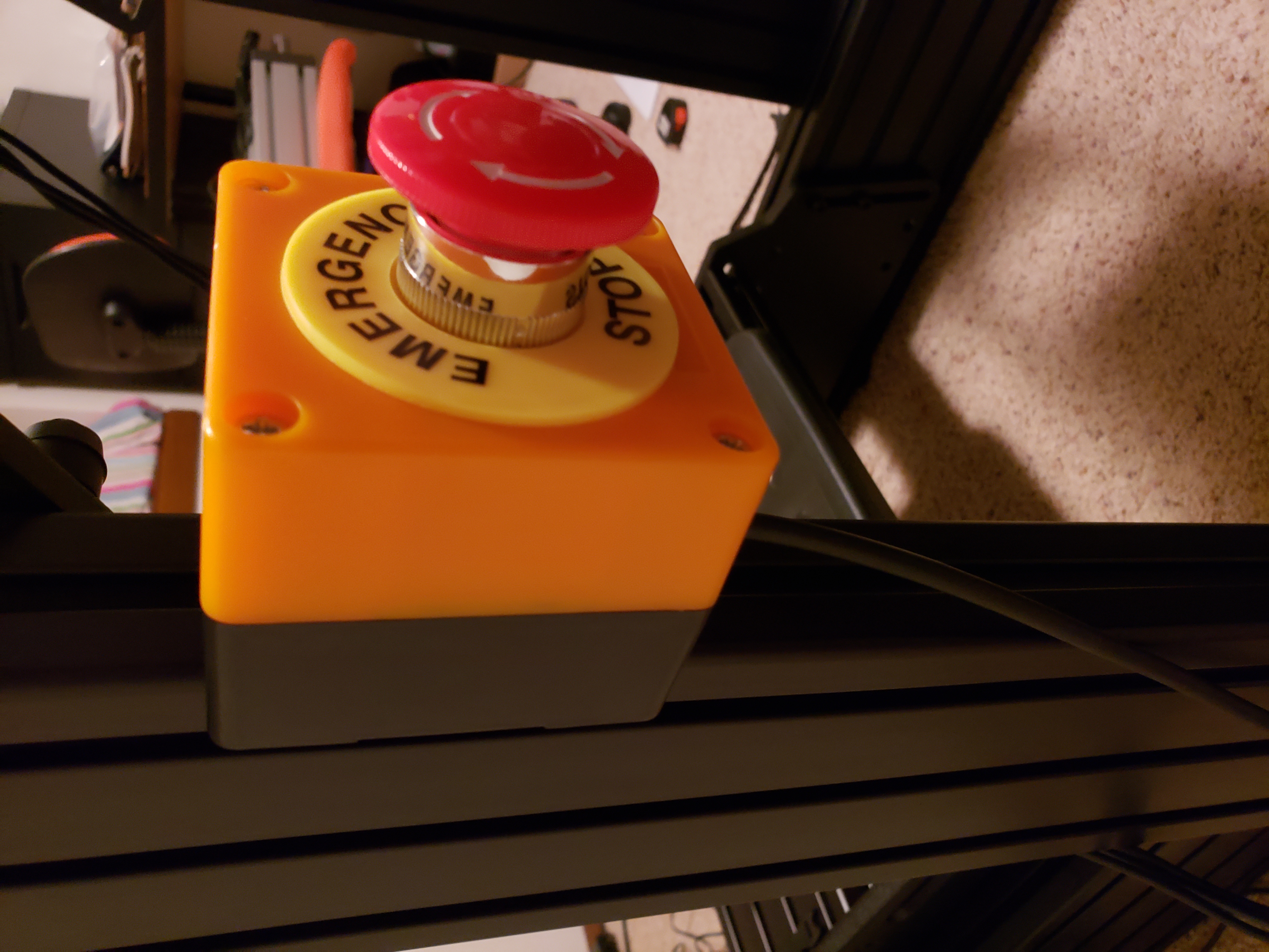
Here’s how the button looks when installed to the rig – but we’ll get to that later:
Note: if you’ve decided to skip the emergency button altogether, you need to add a piece of wire to connect the 2 pins on the emergency button plug in the breakout board. The circuit needs to be closed as otherwise it will be seen as a pressed emergency button and actuators won’t work.
Extra circuit breaker
For extra safety, we can add an additional circuit breaker on the power circuit for motor controllers. If you decide to add it, I recommend splicing the black wire (I’m referring to the inside wire, out of 3: black, white, green) on the power cord segment going from the wall socket to the first controller and adding the circuit there. Preferably close enough to the first controller so that breaker can also be located in the cabinet.

Make sure to crimp the connectors – I highly recommend the insulated version:
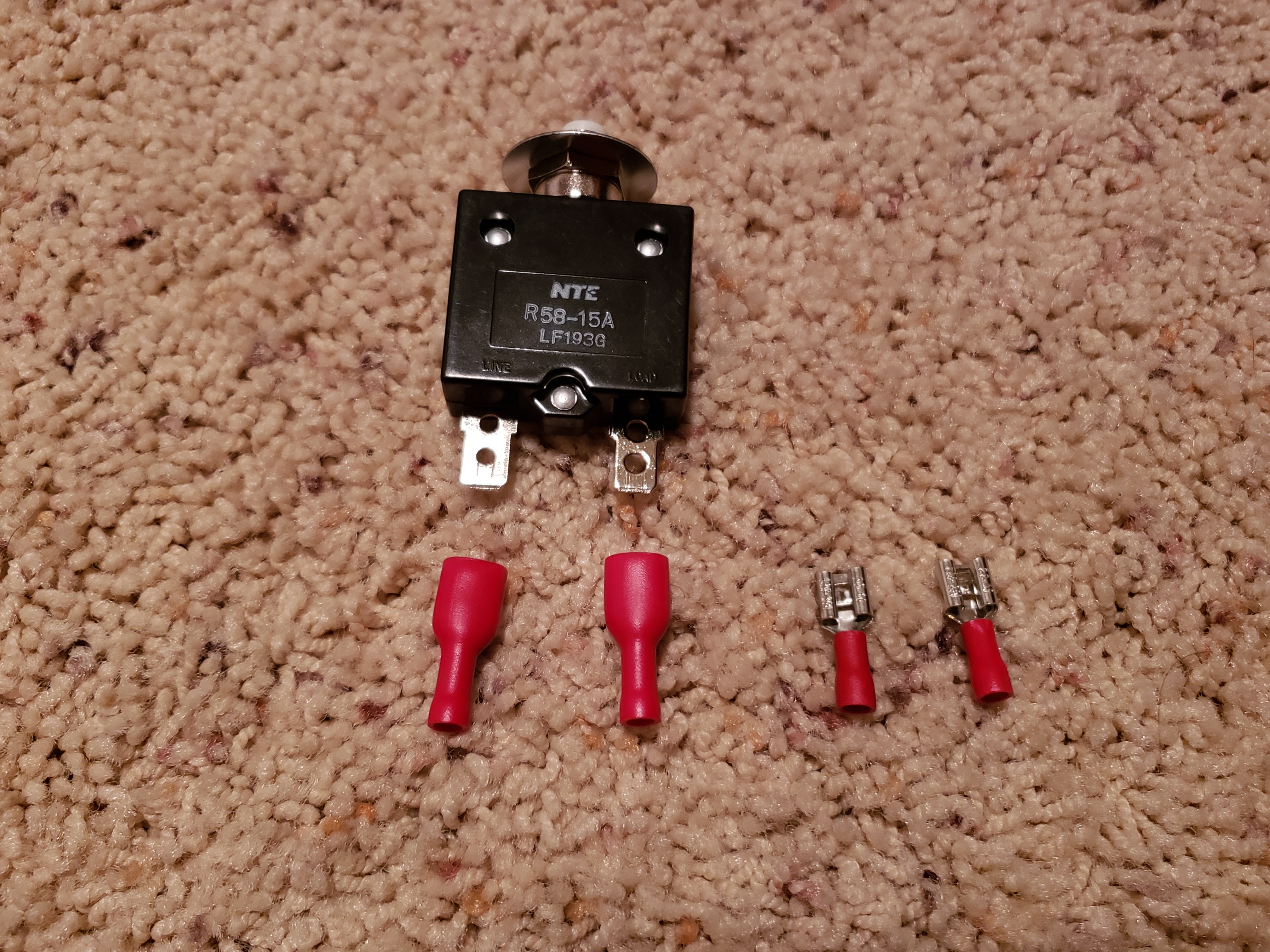

See bill of materials for product links.
Enclosure
As we quickly realize, the controllers take a fair amount of space. Leaving them exposed may lead to accidental damage, expose them to dust and can even be dangerous considering the easily accessible wiring. It’s even more important to safely house them in some kind of enclosure if you have kids or pets.
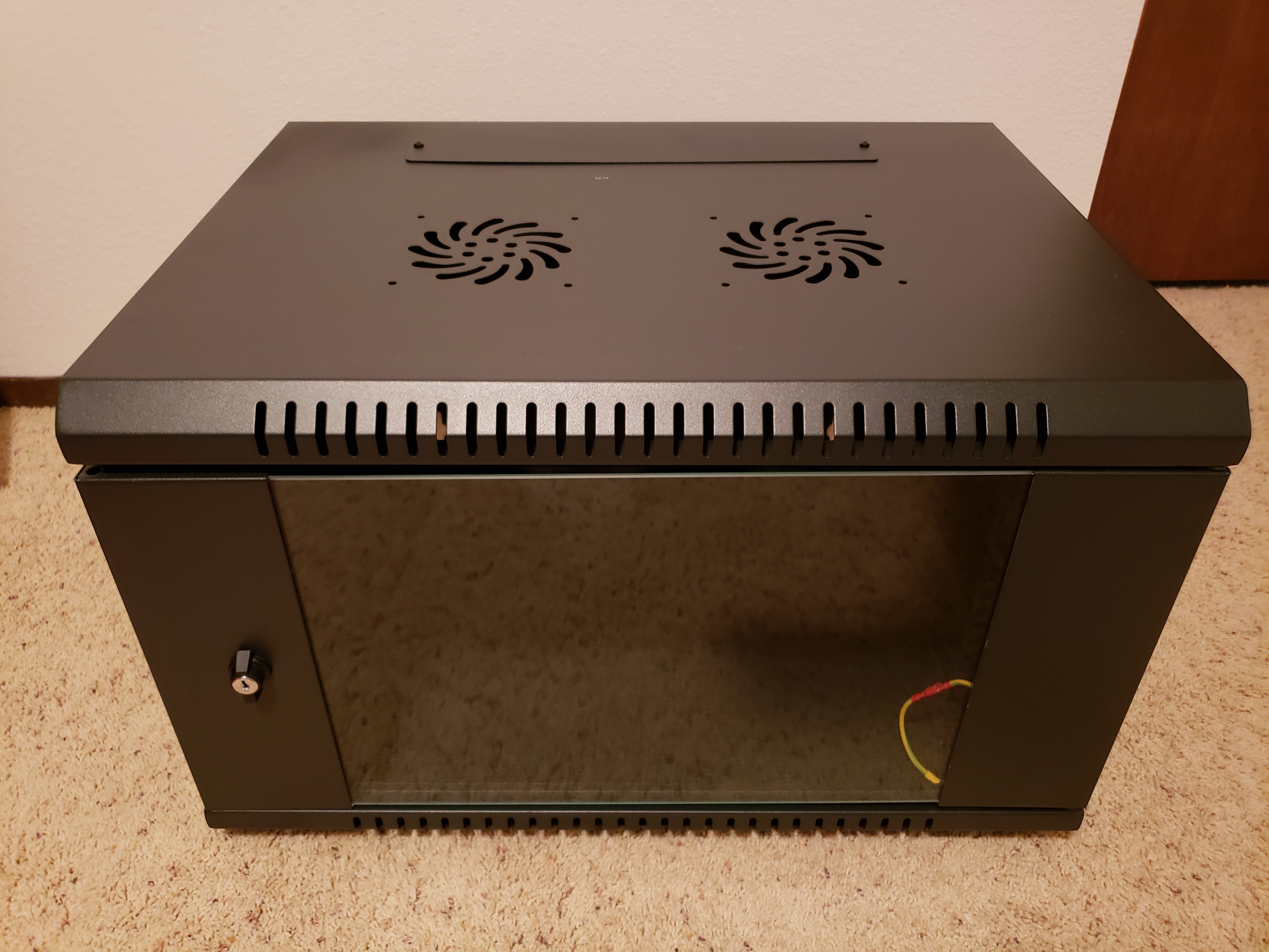
Luckily, server cabinets are a perfect size to put all those electronics in. Now, the perfect size of cabinet depends on your future plans – if you want to keep PC, amplifier and maybe couple additional controllers (for surge, traction loss, belt tensioner…) in the same cabinet, be sure to pick up a larger one.
I decided to use the 6U size. Perfect size to fit 4 controllers and allow me to also safely stash remaining cable lengths, but not too big as to become bulky and unwieldy:
The model I purchased didn’t come with casters. I bought them separately, from the same company to be sure the hole spacing at the base to screw on the casters is right:
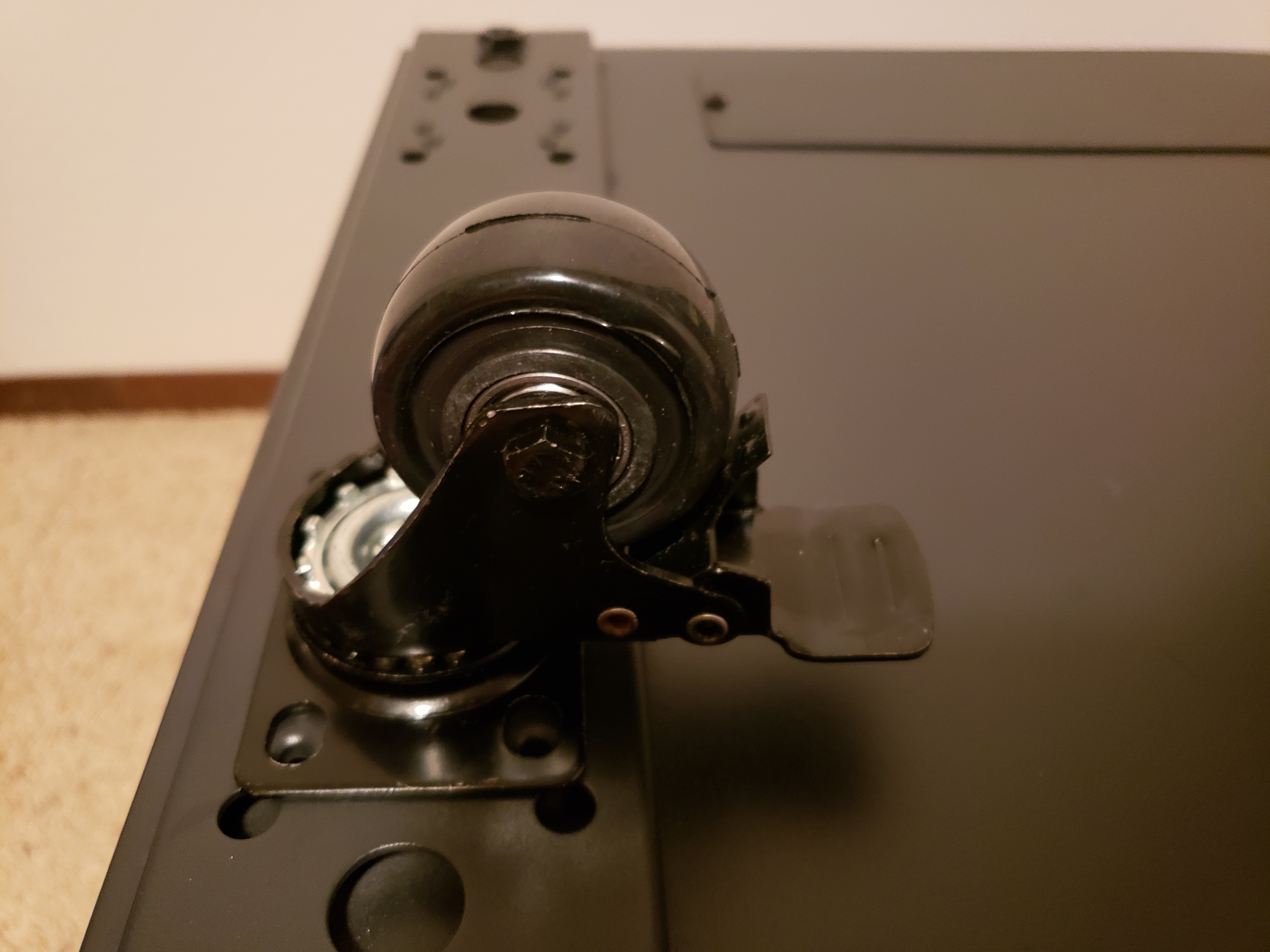
Here’s a quick reference of the hole spacing in case you purchase the same cabinet:

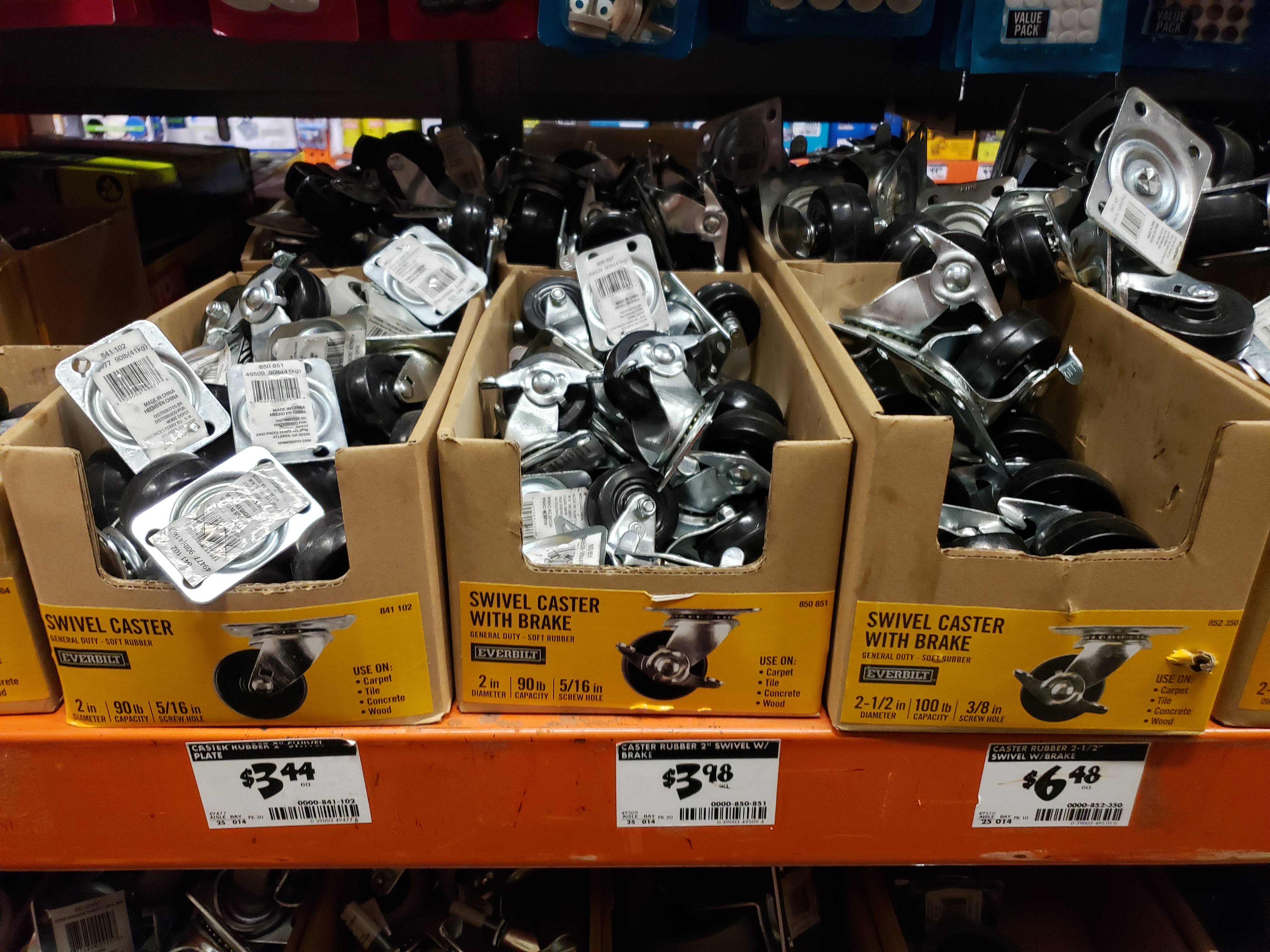
And if you want a slightly better deal, you can pick up a set of casters from Home Depot 🙂
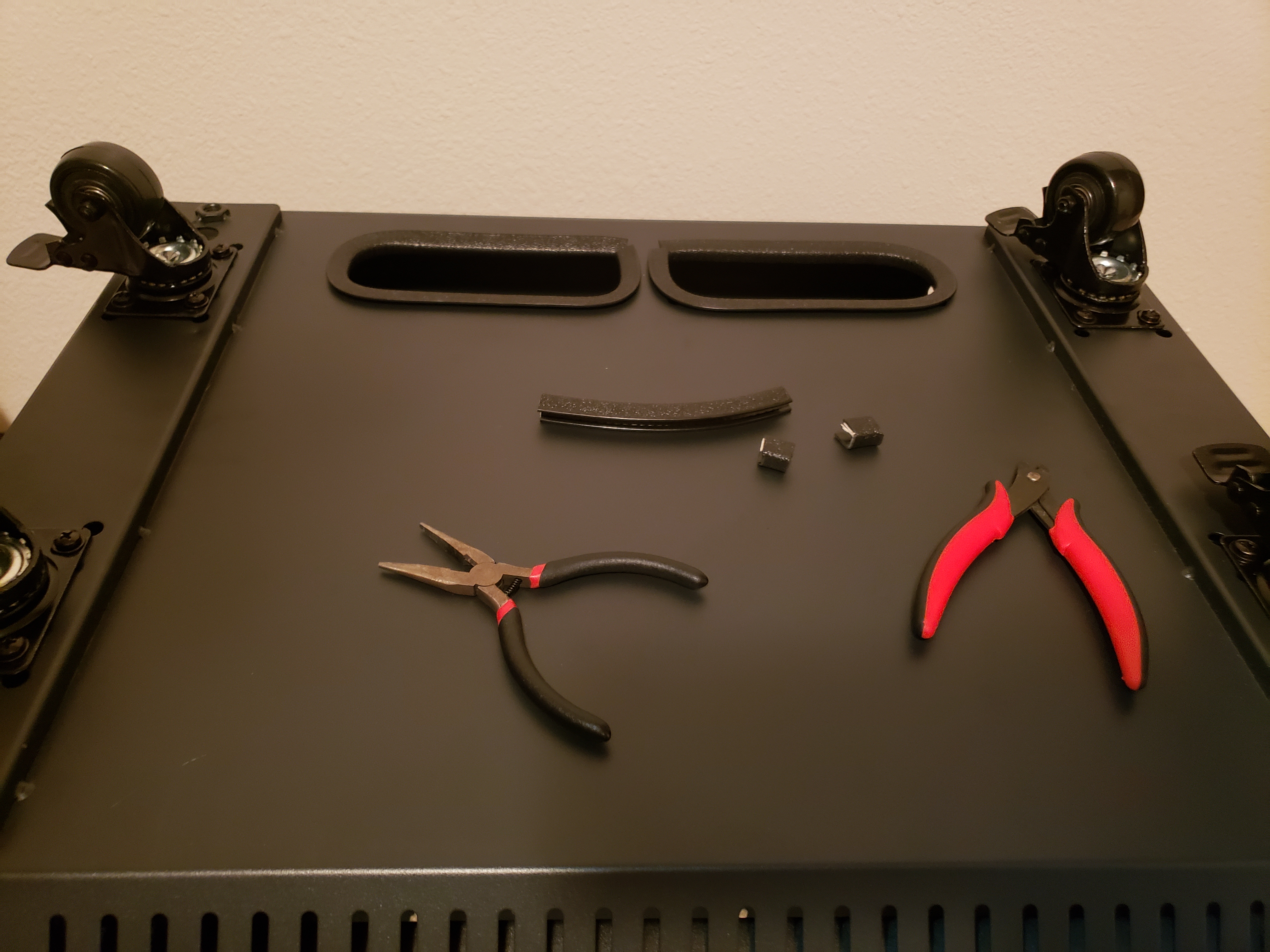
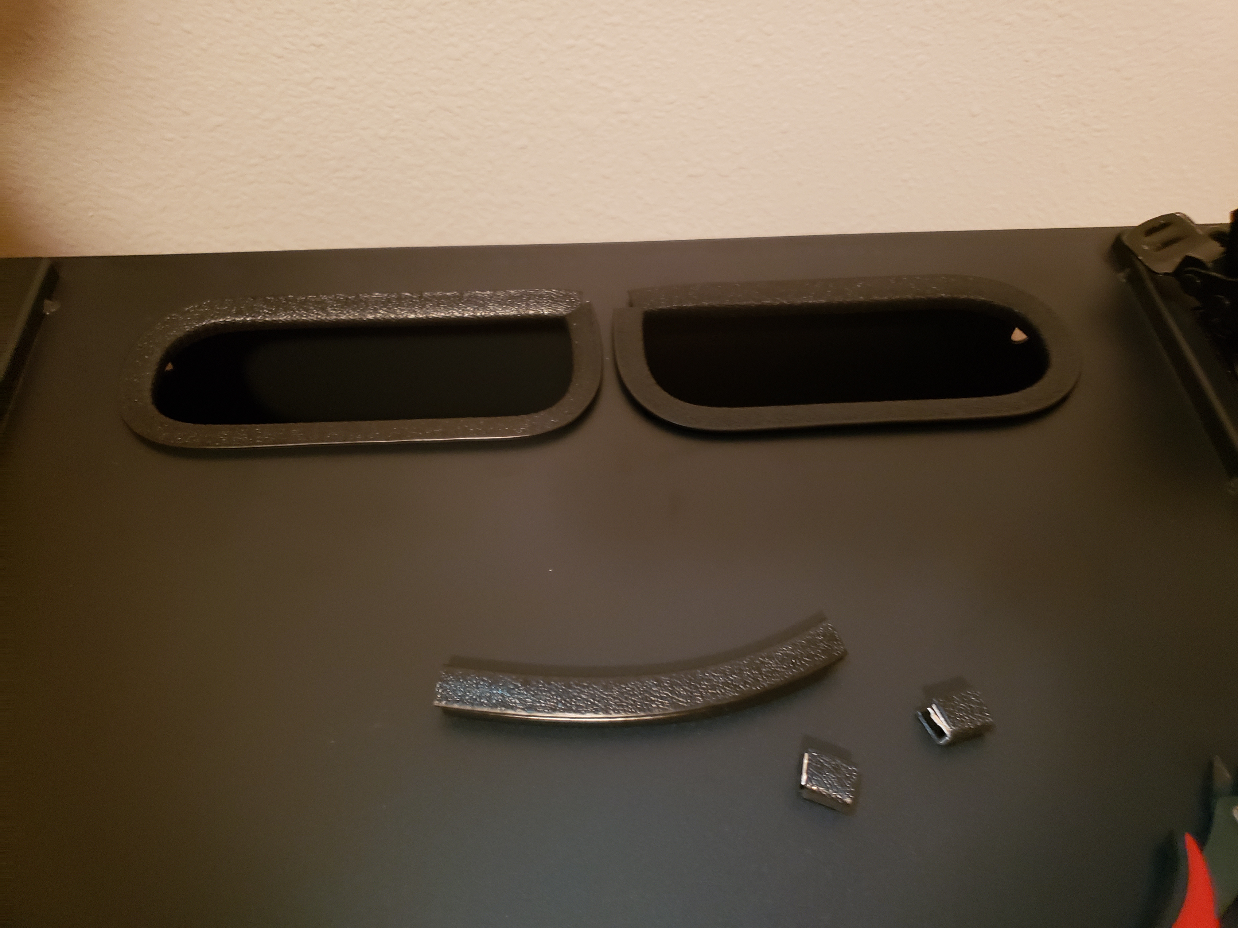
Before installing everything in the cabinet, I needed to decide how will all the cables be routed. There are few openings in those cabinets, and I decided to use the ones at the bottom. However, the cutouts have quite sharp edges, and last thing we need is damaged cable, potentially posing risk of electric shock. Luckily, I had some leftovers of “edge protection strip”, previously purchased for another project (check out my Arcade Cabinet build 🙂 ). This strip is easy to install, can be cut with metal snips and conforms to the shape with just a little extra force. No need to glue it in place, as it will keep its shape.

Alright, with the cabinet ready – time to fill it up with goodies.
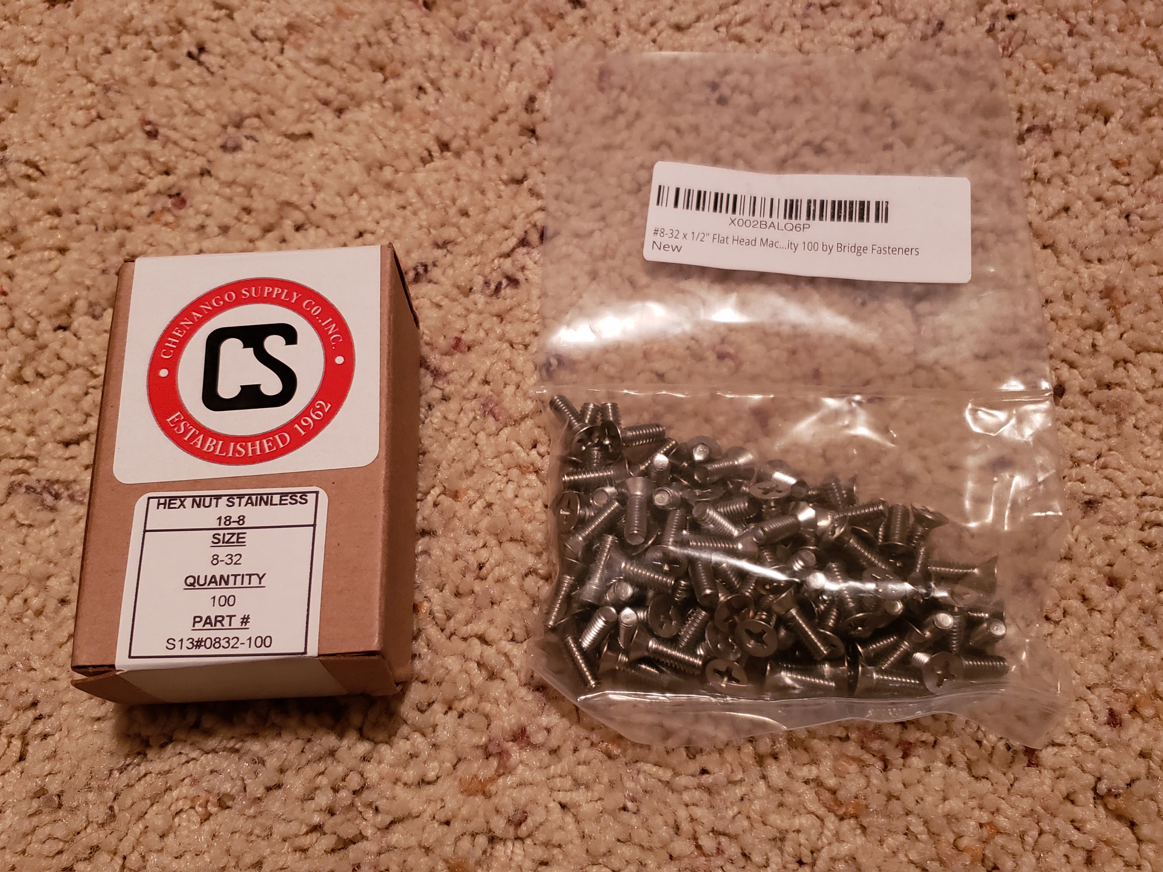
We’ll be installing the controllers onto a 5U mounting plate. It’s perfect size for 4 controllers used by out actuators, mounted vertically in a row. We’ll be using 8-32 bolts and nuts (see bill of materials):

Having all controllers mounted onto the plate, I connected them to motors for a quick test:
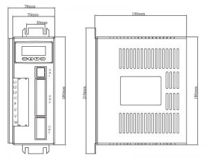
If you’re planning to install the controllers in a different way, here are the dimensions for reference:
Time to install the plate inside the cabinet. The plate with controllers is a bit heavy at this point, so to install it on the rails in the cabinet, I propped it with pieces of scrap wood:
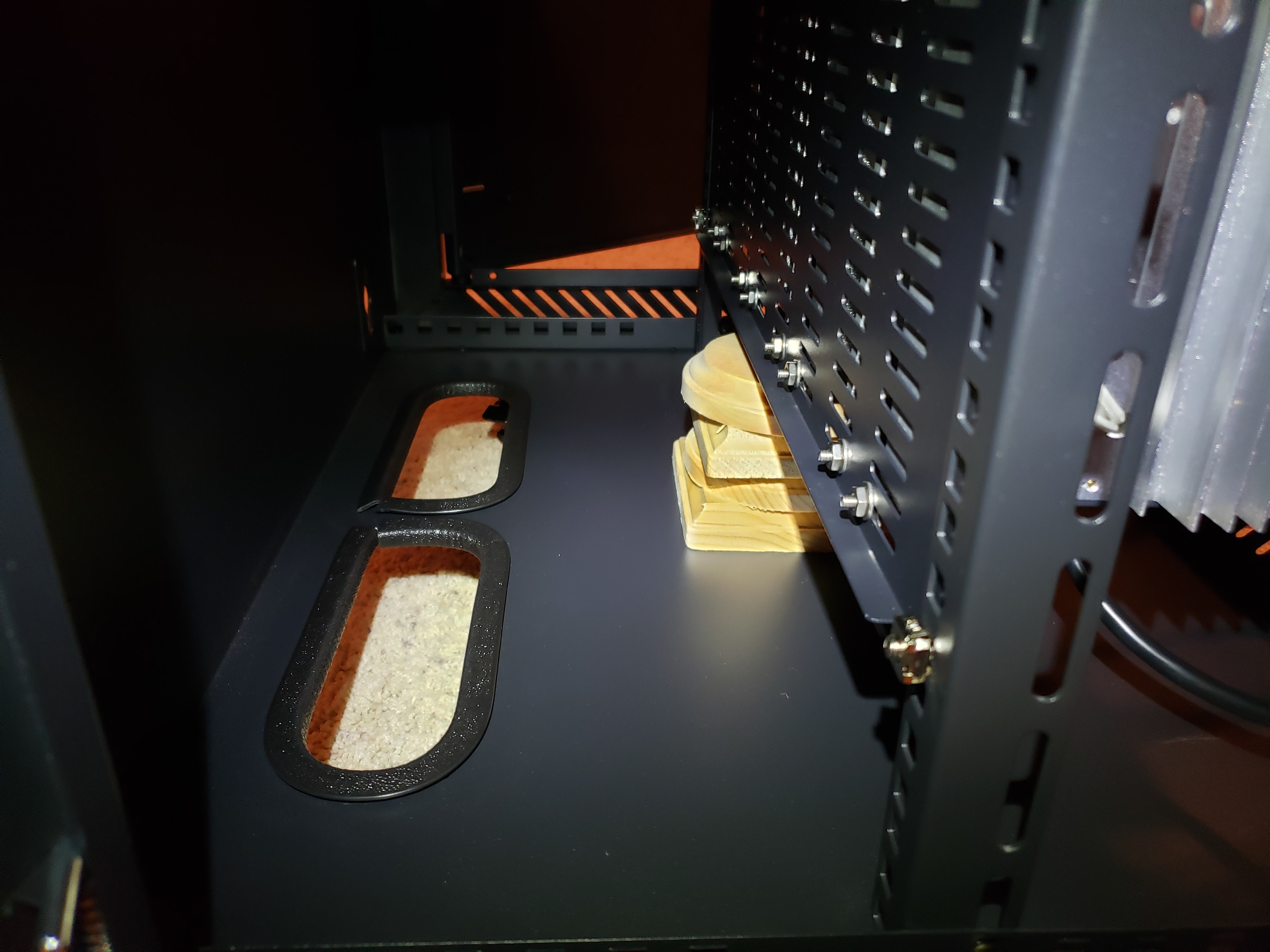
View inside of the cabinet, notice the cutouts in the cabinet’s floor.
This is a good time to route all the cables and attach them to controllers. Next, attach DB25 cables coming from the controllers to the breakout board:

And put it in the enclosure, if you 3D printed one:
Also, don’t forget to wire up the emergency stop button:
If the circuit is not closed through the green connector, actuators won’t work.
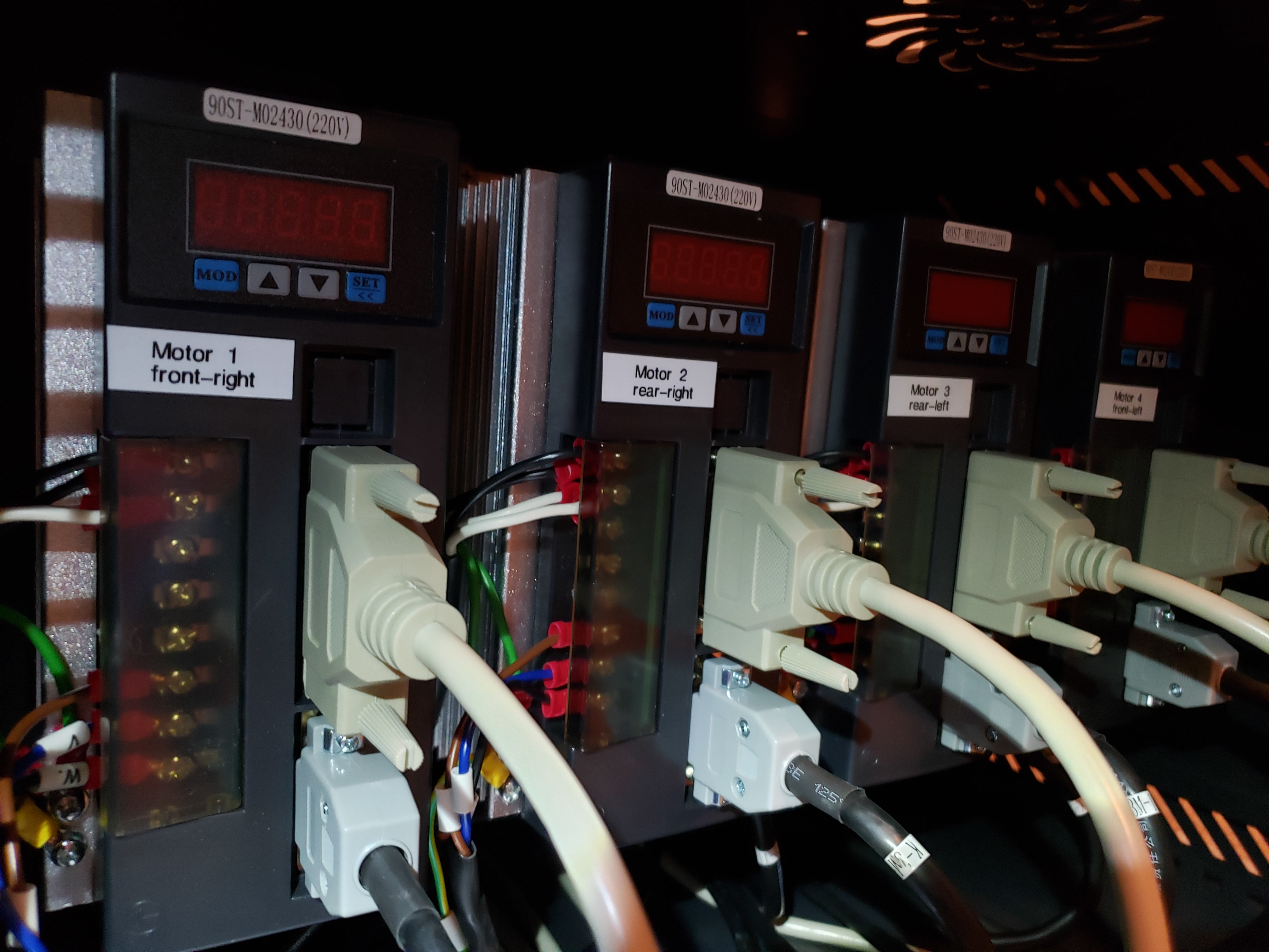
Now the important question is – what’s the order of connecting the controllers to actuators? Which one is which? I printed labels to describe them, and this is the reference:

If you happen to have a label maker – use it! Makes life easier:
Once everything is done, we can appreciate how neatly it all looks:

We’re not done with the full project yet – we still need to build actuators and attach it all to… something. If you don’t have a rig yet, I’ll show you how I built mine as well.
Let’s continue on to:


Leave a Reply