
Idea
The idea for this project was born from a conversation with a friend – he was wondering if creating such game board could help in teaching kids how to play Chess. And I loved the fact that both making the project, as well as then playing using it sound fun 😉 And what a great opportunity to try out some new things that I didn’t have experience with before (i.e. PCB design).
Gameplay and development overview
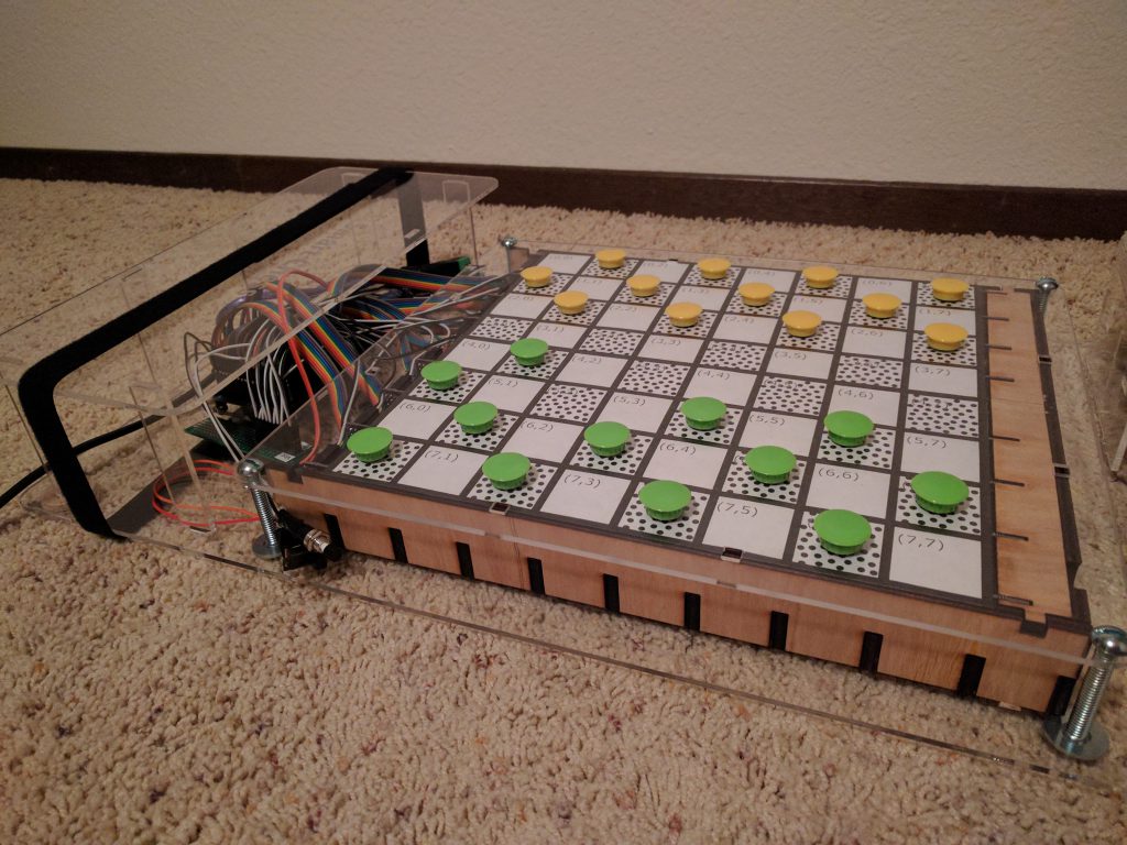
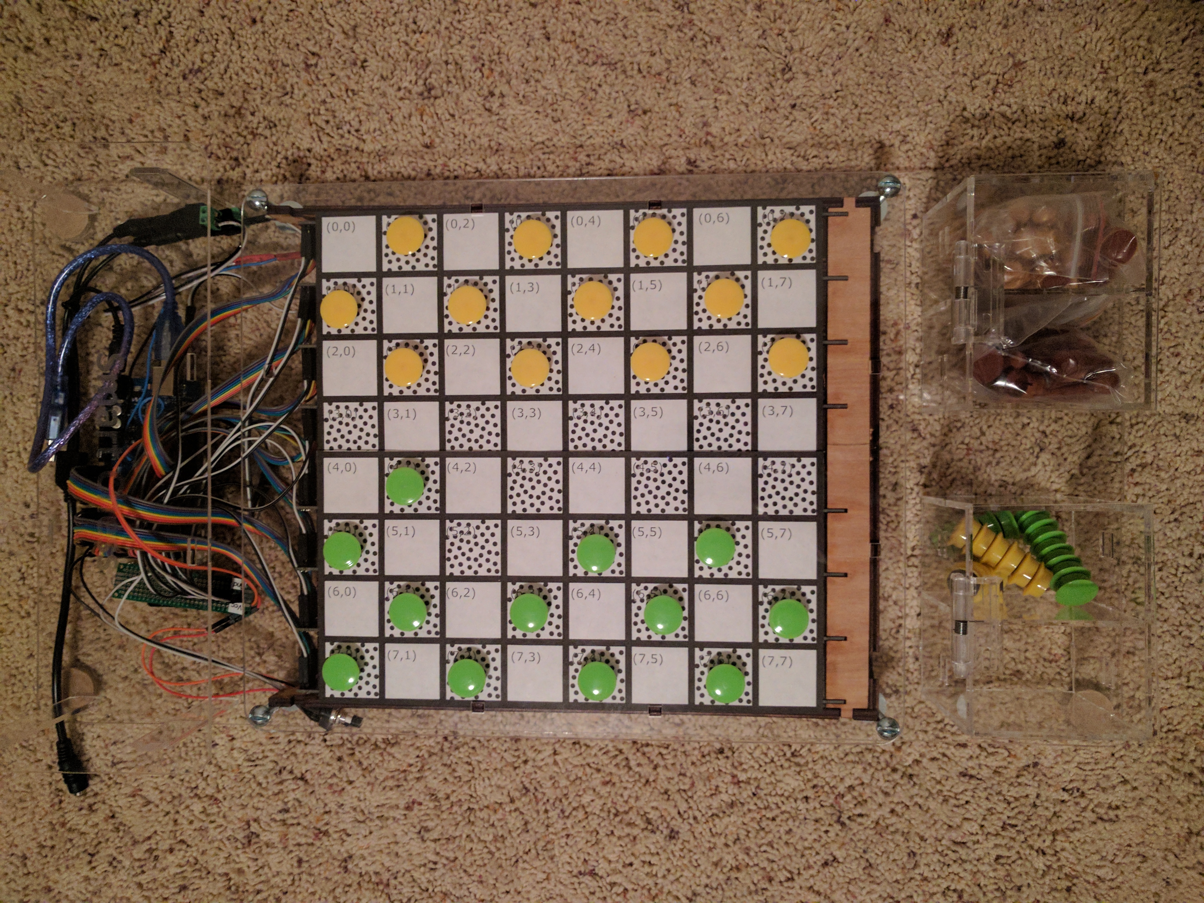
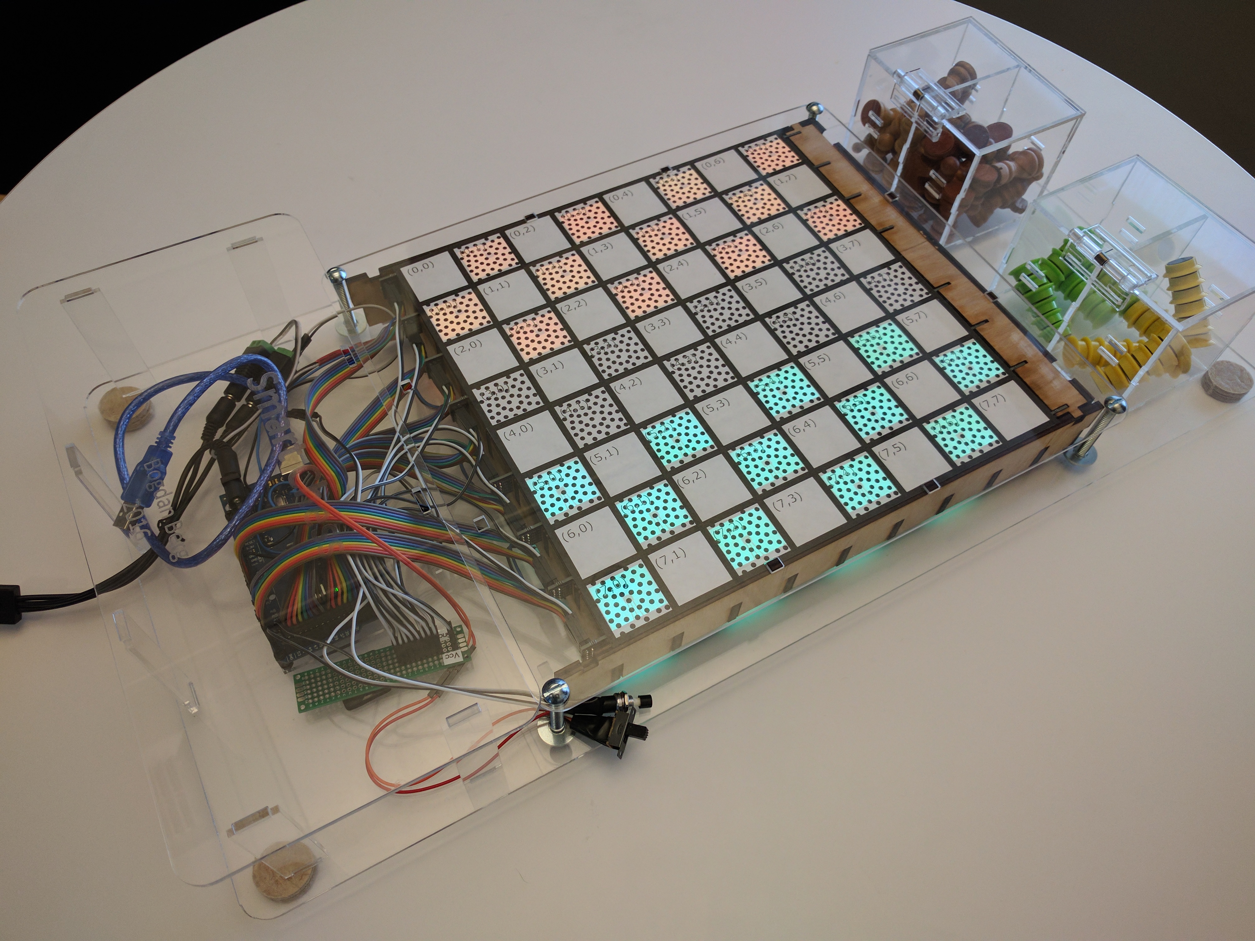
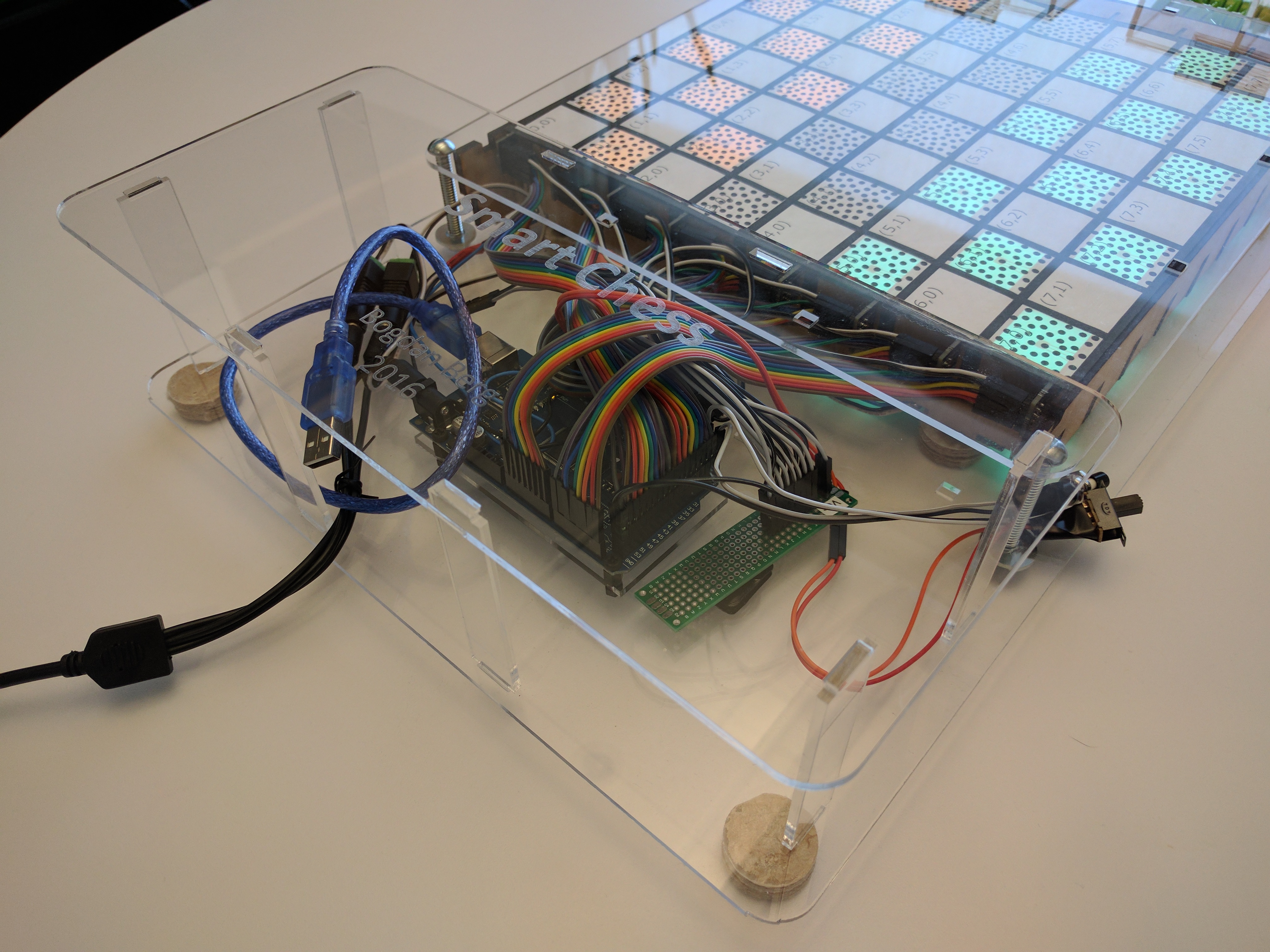
Completed project – photos


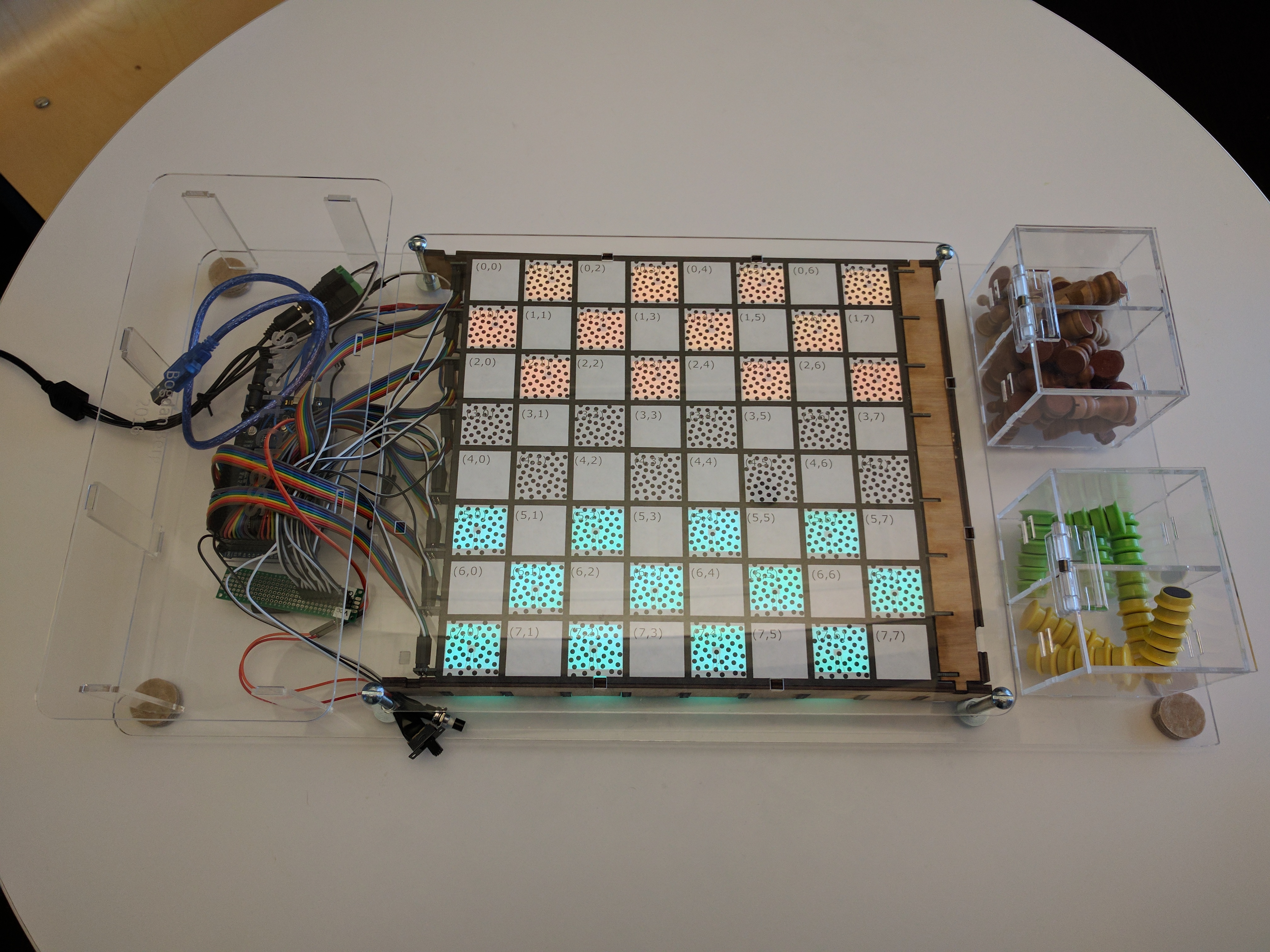
Board game size
- Play area: 10.25 inch x 10.25 inch
- Complete project dimensions (including boxes for game pieces on the side, and room for electronics on the other): 24 inch x 16 inch x 5 inch
What exactly does it do?
Well, it’s a game board – a special one 😉
How is it special, you ask?
It tracks the game state, shows possible moves, indicates when a piece has been lost and should be removed from the board, and best part is: it teaches the game rules and prevents players from cheating! (you can’t make a move that is not allowed…)
So far, I implemented Checkers (the International version), but the code is structured so that it’s easy to add additional games. Next one, time permitting: Chess. Then maybe tick-tack-toe – board is 8×8 so there could be 4 games played simultaneously 🙂 There are a lot of games that can be played on a board of this size!
How long did it take to make it?
Altogether, this project took around 6 months – there isn’t always enough free time to dedicate to side projects, and this wasn’t the only hobby occupying my free time (various other, smaller projects always come to my mind), but I’m always aiming to finish what I start.
I’d estimate that I spent about 20 hours working on the mechanical design (my first project in Fusion 360, half the time was spent on learning the basics), about 10 hours designing PCB (using KiCad, again my first time with this app so there was definitely learning curve there), probably 15 hours or so on soldering and assembly (soldering 64 sensors, 64 resistors, countless number of wires in between it all, gluing acrylic boxes for pieces, etc.) and maybe 15 hours writing software (libraries + first game: Checkers), testing, and tweaking for more pleasant gaming experience.
Overall, I think it took about 60-70 hours from the initial concept to playing with my colleagues at work on the finished board.
I want to build it too!
If you’d like to build something similar by yourself, below you’ll find the list of components I used, and clearly (I hope 🙂 ) documented 3 main stages (mechanical design, electronics, software) in separate blog posts linked below. And don’t hesitate to ask any questions if something is not clear.
This project requires access to laser cutter (some pieces require fairly high precision, i.e. the internal grid sides with the half-cut slots, which can be achieved by other means, but laser cutter makes life easier 🙂 ) and basic soldering skills. All materials can be cut on a laser cutter with bed size 24″ x 18″ or larger (there are pieces in this design very close to those dimensions [base of the board], thus they wouldn’t fit on a smaller bed).
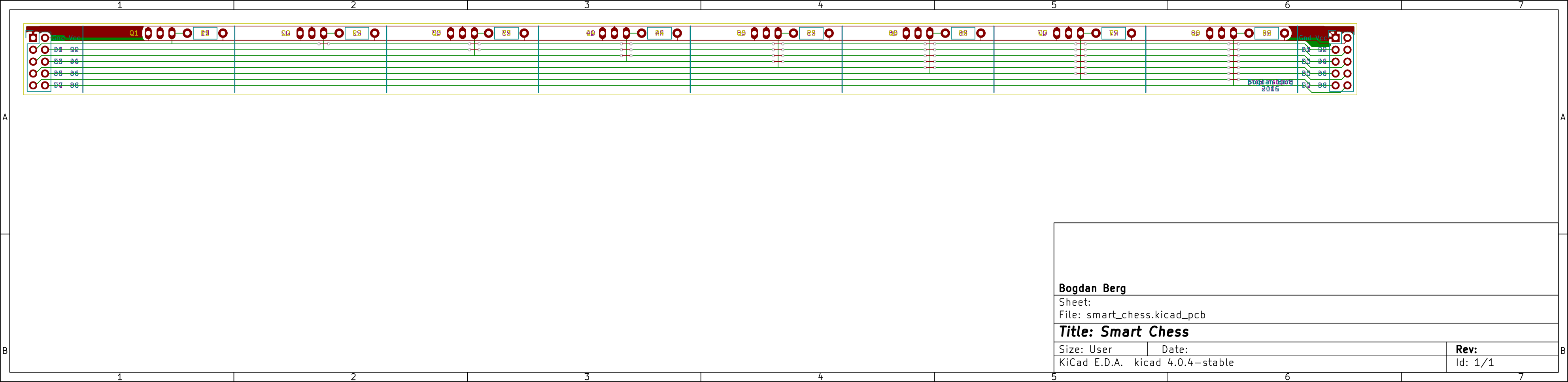
Also, a custom PCB board was used, and is the single most expensive element – more than half of the complete build cost (~$100 for custom ordered PCBs). It’s not required, but I thought it makes for a more clean design (removes the need for extra wiring, also serves as a sturdy mounting plate for the sensors, makes the final assembly feel even cooler!).
Build stages
Parts list
Here’s a list of all used parts, for quick reference. Those parts are also called out in each of the appropriate section in the build stages linked above.
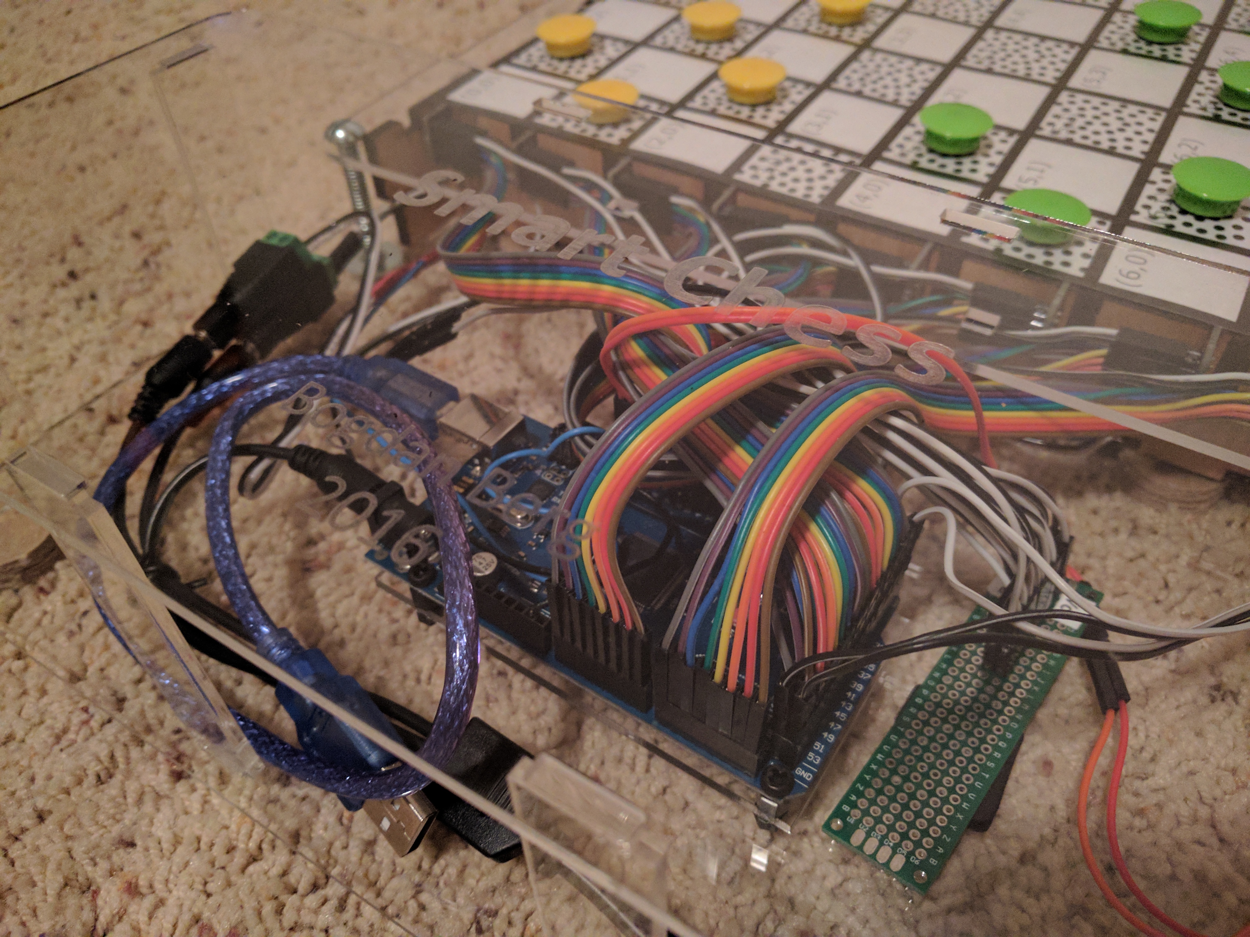
Electronics
- Arduino MEGA – Buy on Amazon
- We’ll be using MEGA, and not i.e. the most popular UNO R3, as we need a lot of I/Os (64 inputs for sensors, outputs for controlling LEDs, any additional inputs i.e. for game reset button, etc.)
- The design could be simplified (i.e. see here), or I/O extenders could be used instead of Arduino MEGA. However, using MEGA also gives us more memory to work with, which comes in handy if we want to implement additional games
- Hall effect sensors (non-latching) – Buy on Amazon
- Quantity: 64 (+few spares just in case)
- Programmable LEDs (WS2812) – Buy on Amazon
- Quantity: 64 (but those are usually purchased in a strip, which is great as we’ll have some spares)
- Note: The strip we purchase has direct repercussions on the design decisions made – the size of game board cells has been selected to match the pitch of LEDs on the strip I purchased. This simplifies the design as we can use the LEDs as they come on the strip (i.e. without the need to re-solder them to achieve any other spacing), and makes the build simpler/faster. For the below strip I used, the pitch is 1.28 inch and the design follows this assumption.
- Magnets
- Requirements: magnets need to fit in the board cell (thus no bigger than the pitch between cells/LEDs), be strong enough to affect the hall sensors, yet at the same time be weak enough to allow magnets be positioned on adjacent cells, without repelling each other
- Link: I found out the best magnets for this project can be found in Daiso (Japanese version of dollar store, everything is $1.50 unless marked otherwise 🙂 ) – they have sets of colorful magnets, 12 in each pack (which just happens to be exactly the number of required pieces per player in checkers!)
- Resistors – Buy on Amazon
- We need a resistor for each hall effect sensor. Those will be soldered onto the custom PCB to make assembly easier. 10k Ohm will work well.
- Power supply – Buy on Amazon
- 5V, at least 5A to have a safe buffer with all LEDs lit up
- DC power jack (male + female) – Buy on Amazon
- DC power jack splitter: 1 female – 3 male – Buy on Amazon
- Hook-up wires – Buy on Amazon (solid core hook-up wires), Buy on Amazon (highly recommend getting few packs of those, very useful)
- 2 lines – for power+ ground from main rail to each custom PCB for hall sensors
- 8 lines – for signal between Arduino and hall sensors
- Straight headers – Buy on Amazon
- Not required, wires can be soldered directly to the PCBs, but I like the finished look and clean assembly process (when everything pops into place 😉 )
- Perfboards, or prototype PCBs – Buy on Amazon
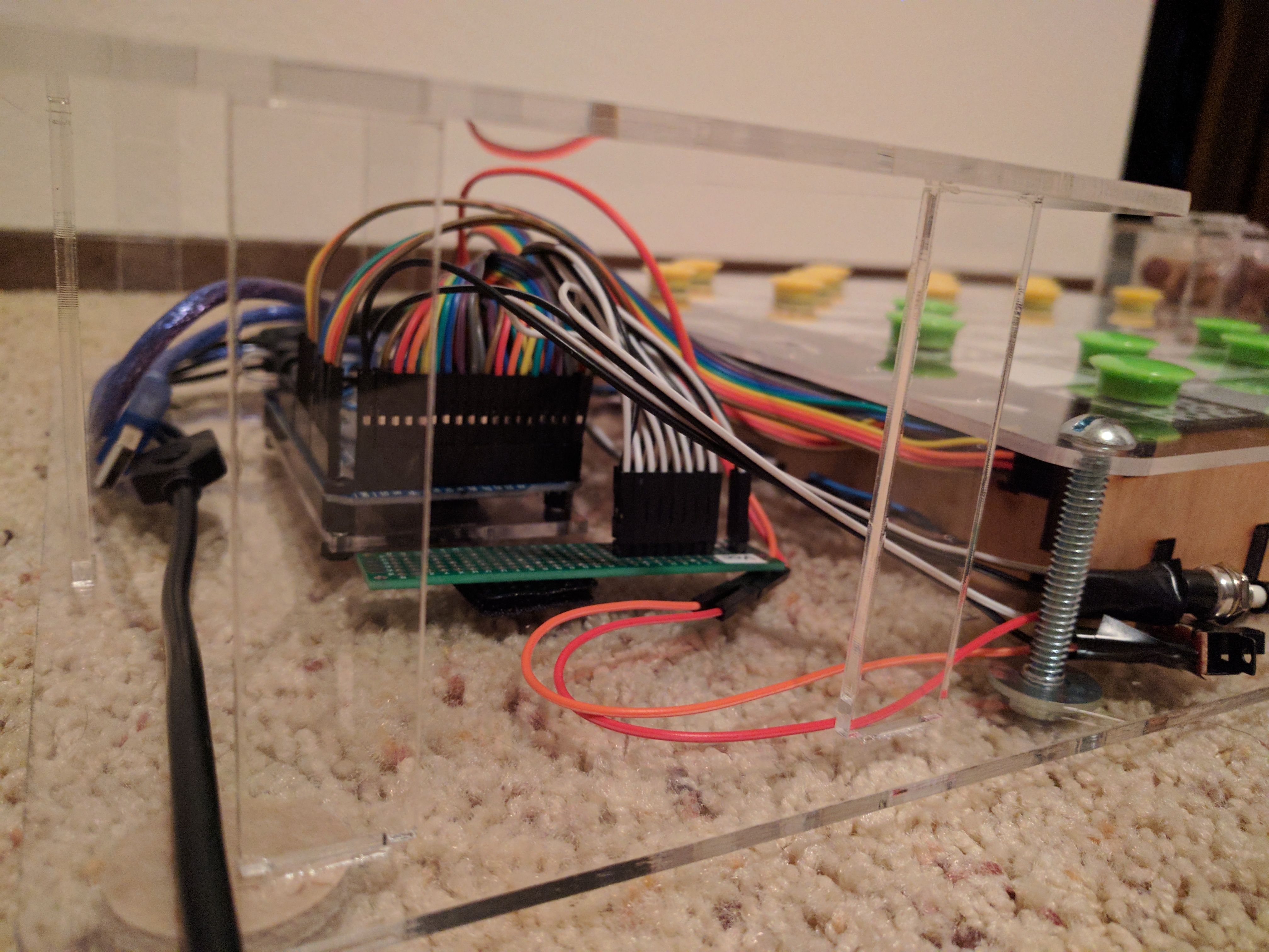
- I used a universal PCB as a rail for Vcc + ground, for more neat look and easier final assembly (see build photos for more details)
Materials
- Acrylic – Buy from TAP Plastics
- 1/8 inch thick, extruded acrylic (cheaper than cast acrylic, and we won’t be etching that much to see any difference)
- Use sheet dimensions matching the bed size of your laser cutter (in my case, 24″ x 18″, and I ended up using 3-4 sheets, considering that I made some design changes in the process)
- Acrylic cement – Buy from TAP Plastics
- Smallest bottle you can buy will be more than enough
- Acrylic cement applicator – Buy from TAP Plastics
- I prefer smaller applicators (thinnest needle, smallest risk of dripping, etc.)
- Plywood
- I used 5mm thick plywood from Home Depot (sold as ‘underlayment’)
- You can get it in sheets 2′ x 4′ and even bigger – but you can get it cut to desired
- Bolts and nuts – Buy on Amazon
- We only need the biggest bolts from this set (1/4″-20 x 2″), but the set has 2 of them, and we need 4 – so either we’d need to order 2 sets, or pick just the bolts needed i.e. from Home Depot (cheaper option 🙂 ). Those bolts are used to attach the top “lid” of the board to the base (and this is also how the internal grid is being kept together).
Tools
- Phillips screwdriver (only for attaching DC jack adapters)
- Soldering iron, solder (fume extractor and “third hand” optional 😉 )
- Electronic calipers – always measure your stock…
- Pliers
- Wire stripper
- Acrylic cement applicator
- Masking tape, rubber bands – helpful during assembly, to keep various pieces together (i.e. when gluing acrylic)
Misc
- Chess pieces – Buy on Amazon
- Checkers pieces – Buy on Amazon
- Furniture felt pads
- We’ll use those under the base as a padding to make sure the game board won’t scratch surfaces it’s used on (as there are bolts sticking out underneath).
- You can buy those cheaply from local hardware stores, Amazon, etc. I recommend going with about 1 inch diameter.
Cost
In my case, including extra materials used fow few iterations of various components as the design was changing, the total cost reached almost $300 (including two iterations of custom PCBs which resulted in a bill of almost $150, and original, unsuccessful attempt in soldering everything without the PCB – too many wires everywhere to keep it clean and practical 🙂 ). Now, having the design figured out, I think the cost shouldn’t exceed ~$150-$200.
Obviously, the cost highly depends on what you have available at hand, which materials/components you use and what needs to be purchased.
Also, once you splurge on the missing pieces, you’ll still have plenty of components left when done with this project (resistors, headers, wires, etc.).
Questions? Feedback?
Are you interested in this project and have any questions? Have an idea on how to make it even better? Did you build something similar that you’d like to share? (If you decide to try and replicate my build, I’d appreciate the mention!)
Or maybe you happen to have a factory at your disposal and would love to bring this project to manufacturing? 🙂
Leave a comment and I’ll get back to you!


Leave a Reply